Facebook
 Google
 GitHub
 Linkedin
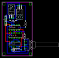
Did you connect the power and ground pins as shown in the board layout?
IC1 (4017) - pin 8 to ground, pin 16 to +12v
IC2 (4075) - pin 7 to ground, pin 14 to +12v
IC3 (4093) - pin 7 to ground, pin 14 to +12v
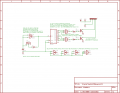
Sorry I forgot to mention that the schematic doesn't show the power and ground pins. The software automatically handles those connections and they're not shown in the schematic to reduce "clutter". They are, however, shown in the board layout.
Beware of static electricity; CMOS circuits are very vulnerable to static discharge. Sorry I didn't mention that sooner; I live in Florida and it's so humid that static isn't a problem here, so I tend to forget about it.
IC1 (4017) - pin 8 to ground, pin 16 to +12v
IC2 (4075) - pin 7 to ground, pin 14 to +12v
IC3 (4093) - pin 7 to ground, pin 14 to +12v
Sorry I forgot to mention that the schematic doesn't show the power and ground pins. The software automatically handles those connections and they're not shown in the schematic to reduce "clutter". They are, however, shown in the board layout.
Beware of static electricity; CMOS circuits are very vulnerable to static discharge. Sorry I didn't mention that sooner; I live in Florida and it's so humid that static isn't a problem here, so I tend to forget about it.
 I really shouldn't attempt these things when my caffiene stream is too high in blood content, particularly in the wee hours of the morning... I've corrected that post.