 Facebook
 Google
 GitHub
 Linkedin
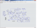
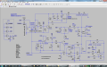
You added a diode? Could you post an image of that so I can take a look?Looks good. I added a diode to turn off the pwm at the end and hooked it up to the +12.
How about just a dpst switch on the coil to switch it in and out.
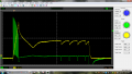
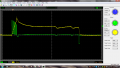
Electromagnet waveform
- Thread starter cmartinez
- Start date


")
| Thread starter | Similar threads | Forum | Replies | Date |
|---|---|---|---|---|
| A | Electromagnet | General Electronics Chat | 92 | |
| R | Electromagnet Turns And Same Field generated?? | General Electronics Chat | 5 | |
| S | Electromagnet wpt magnetic core | General Electronics Chat | 59 | |
| B | Super capacitors for electromagnet? | Power Electronics | 27 | |
| E | Building an electromagnet | General Electronics Chat | 3 |


