Electromagnet waveform

Thread Starter

cmartinez

Joined Jan 17, 2007
8,762
More like a block diagram, but you can get an idea of the difference in timing.
I used 24 volts and a .6 ms pulse for the high current then pwm for the hold current.
I haven't figured out how not to clamp it at turn off yet. Do you think it needs to turn off fast or just on fast?
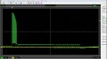
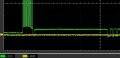
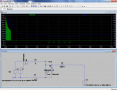
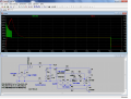
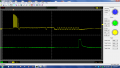
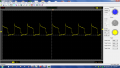
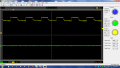
It needs both, this application is time critical since it's for a dispenser. At the end of the cycle the time taken for the current to reach zero is about 0.2 ms.
 

Thread Starter

cmartinez

Joined Jan 17, 2007
8,762
Let me understand this... you're trying to replicate the waveform of the current, controlling voltage in a different way from the one I posted?
Is this what @wayneh was referring to in post 12 of this thread? I thought that everything should be replicated exactly for it to work right. But I might be wrong, of course.
As a reminder, the machine's general power supply is 12V, not 24V, but I can always build a 24V regulated power supply, if there's need.
 

Alec_t

Joined Sep 17, 2013
15,119
You can get the high volts for the initial ramp using a simple switcher. Here's a sim which replicates reasonably well the initial pulsed 120V (-ish), the current ramp and the switch-off negative voltage spike. Voltage across the valve coil is shown in yellow and the coil current in blue. I haven't modelled the PWM-ed 4A plateau.
SwitcherTest.gif

Edit: The A06408 FET shown won't handle the switcher voltage; it was just an arbitrary model choice to show the switcher function.
 

Attachments

Last edited:

Thread Starter

cmartinez

Joined Jan 17, 2007
8,762
You can get the high volts for the initial ramp using a simple switcher. Here's a sim which replicates reasonably well the initial pulsed 120V (-ish), the current ramp and the switch-off negative voltage spike. Voltage across the valve coil is shown in yellow and the coil current in blue. I haven't modelled the PWM-ed 4A plateau.
View attachment 81637

Edit: The A06408 FET shown won't handle the switcher voltage; it was just an arbitrary model choice to show the switcher function.
Thanks! That curve is almost exactly what I'm looking for... it even has the -75V at the end! Is that because of inductive kickback?
I'm going to start playing with your circuit in LTspice and try to understand how it works. I seriously doubt I can accomplish the 4A plateau without more help, though... thanks again!
 

Thread Starter

cmartinez

Joined Jan 17, 2007
8,762
Here's another screenshot I have from previous measurements (ignore the yellow trace)

It shows that the pulses start peaking at 120V then down to about 85V, and at the end go below 0V for 0.1ms (seems about -5V in the graph) and then the plateau goes to approximately 6V. The 28 kHz pulses never reach zero volts but rather reach bottom at around 10V
I'm under the impression that those pulses are generated by discharging a capacitor that was loaded with 120V and the coil's other pole is somehow referenced to a 6V source... so it seems I was wrong, the plateau is 6V not 12V as I had mentioned earlier. The next pulses after the plateau seem to oscillate between +6V and -6V. The final -75V pulse is not shown here due to the way I hooked the oscilloscope in this measurement.
 

Attachments

#12

Joined Nov 30, 2010
18,224
I thought that everything should be replicated exactly for it to work right.
At the risk of bring wrong, I disagree. Occam's Razor. What solenoid designer would intentionally create a valve that needs 2 or 3 power supplies when you know a dozen uses for solenoids that only require one voltage? I think you're chasing the artifacts of a single voltage driver. The drive may be chopped, and that's what's causing inductive kicks all over the place, but I think you're making this way too complicated.

Just my 2 cents.
 

Thread Starter

cmartinez

Joined Jan 17, 2007
8,762
At the risk of bring wrong, I disagree. Occam's Razor. What solenoid designer would intentionally create a valve that needs 2 or 3 power supplies when you know a dozen uses for solenoids that only require one voltage? I think you're chasing the artifacts of a single voltage driver. The drive may be chopped, and that's what's causing inductive kicks all over the place, but I think you're making this way too complicated.

Just my 2 cents.
I agree... it's just that I first like to look at a problem from all possible angles first, even the (apparently unnecessary) complicated ones... then I work my way down trying to simplify things. The drawback is that a lot of time is spent (wasted?) during the process. But I tend to do that sort of thing only on problems that lie outside my area of expertise... and this one's burning all the hairs on my head and face...
 

Alec_t

Joined Sep 17, 2013
15,119
the -75V at the end! Is that because of inductive kickback?
Yes. It's clamped by diode D2, which I modelled to have Vfwd=70V.
Without the Ch1 ground reference, it's hard to determine voltages in those pics.
I would hazard a guess that the various voltages (except the -75V) are derived from 12V by a switch-mode power-supply that is controlled according to the needed current profile.
 

Thread Starter

cmartinez

Joined Jan 17, 2007
8,762
Yes. It's clamped by diode D2, which I modelled to have Vfwd=70V.
Without the Ch1 ground reference, it's hard to determine voltages in those pics.
I would hazard a guess that the various voltages (except the -75V) are derived from 12V by a switch-mode power-supply that is controlled according to the needed current profile.
I take as a 0V reference the flat line just prior to the initial 28 kHz pulses, if I were to disconnect the probe and connect it to ground, that's where 0V would be.
 

Alec_t

Joined Sep 17, 2013
15,119
Here's a sim for you to play with.
Current-controlled-switcher2.gif
The valve current profile, including the peak and hold sections, is modelled as I would expect the valve to be driven (but having the advantage of a faster current rise time in valve coil L2 than your existing system provides), although the high voltage waveform HV bears little resemblance to what you show, because in my sim L2 is low-side switched instead of high-side as it seems is done in your system. The HV is generated from 12V by switcher L1/M1. The M1 gate voltage is PWM-ed by comparing a tapped off voltage thr with a 10V 28kHz triangle wave, so with the R3/R4 values shown results in HV being limited to ~120V. However, the required current for L2 can be obtained with HV as low as ~80V. Following a valve energisation, ~2.5mS is needed for HV to recover to the 80V level before another energisation. Voltage s across Rsense is a measure of coil current and is compared with a current-profile voltage (modelled by OR-ing the outputs of V3,V4) to PWM the gate of M2 and so control the current to follow the profile.
 

Attachments

ronv

Joined Nov 12, 2008
3,770
This one seems to pretty well duplicate it. The pulse current is to high and the pulse voltage goes a little to low because of that. But if that PWM was current controlled that would probably fall in line with yours. Again, It is just kind of a block diagram. Maybe when it is all sorted out Alec_t could design some logic for it.

Edit:

How often does it need to fire. Like once every 20ms or once a second?
This might say something about the high voltage supply.
 

Attachments

Last edited:

Thread Starter

cmartinez

Joined Jan 17, 2007
8,762
Thank you so much, Alec_t and ronv for your designs, they're absolutely far more than what I could've accomplished alone by myself... which is probably close to nothing. I'm going to study them closely and start playing with them, see if I can get a better understanding of how they work. Thanks again!
 

Thread Starter

cmartinez

Joined Jan 17, 2007
8,762
This one seems to pretty well duplicate it. The pulse current is to high and the pulse voltage goes a little to low because of that. But if that PWM was current controlled that would probably fall in line with yours. Again, It is just kind of a block diagram. Maybe when it is all sorted out Alec_t could design some logic for it.

Edit:

How often does it need to fire. Like once every 20ms or once a second?
This might say something about the high voltage supply.
It needs to fire around every 20 ms.
Your circuit seems to work fine at the startup pulses when the coil's voltage is measured referenced to ground (green trace) but voltage shoots down to about -20V when it's measured referenced to the other side of the coil (blue trace).
 

Attachments

ronv

Joined Nov 12, 2008
3,770
It needs to fire around every 20 ms.
Your circuit seems to work fine at the startup pulses when the coil's voltage is measured referenced to ground (green trace) but voltage shoots down to about -20V when it's measured referenced to the other side of the coil (blue trace).
Yes, I convinced myself that was how your picture was made since it showed about 10 volts across the coil at low power when the coil is only .62 ohms. (16 amps)
If measured to ground it is 10 volts across about 3 ohms which made it fit. (3.2 amps)
If your saying the ground clip was on the bottom of the coil, it doesn't fit.
 

Thread Starter

cmartinez

Joined Jan 17, 2007
8,762
Here are three original scope readings, The first one is a two channel measurement (with a 1 ms time division) in which one probe (yellow trace) was attached to the top electrode of the coil, and the other probe (green trace) was attached to the bottom electrode of the coil. Both probe's ground clips where attached to the machine's ground. The yellow trace shows how the pulses are fed into the coil, while the green trace only shows the final 75V pulse on the other side of the coil.
The other reading shows the same scenario but with the coil completely disconnected from the circuit (the time division is set at 40 ms. You can see cycle repetitions every 60 ms), the probes are attached to the connector, not the coil, and are grounded to the machine's chassis.
Finally, the third image shows the same reading from the disconnected coil, with just one probe attached to the top (positive) cable in the connector, and the probe's ground clip is attached to the bottom (negative) cable in the connector, it's not grounded to the machine's chassis.
I've been staring at those traces for weeks, burning my brains, and as of yet I haven't figured heads from tails ...
 

Attachments

Alec_t

Joined Sep 17, 2013
15,119
Is Image 02 what you are referring to as the 'third image' ?
Both scope channels are set to "x100". 100 times what?
Does the machine include a SMPS generating the high voltage from 12V, or is the 120V mains-derived ?
 
Top