Facebook
 Google
 GitHub
 Linkedin
I'm not sure if this is the right place to post this, but hey.
Background:
I have been working with Shortbus on some electronics for his EDM mechanics. We started out trying to make it as fast as possible and with all the bells and whistles of a big boy machine. Needless to say this one got pretty complicated pretty fast so where I ended up was a simpler version that will run (I hope) at about 1000 arcs per second. There are a few constraints that seem to limit this. The first is his transformer is rated at 75 volts RMS at 15 amps - yes a brute. This gave us about 95 volts after rectification and filtering. Since it drives a 40,000 ufd cap I thought it best to follow the recommendations to derate it by 40% so 9 amps or so. The targeted arc current is around 35 amps so this limits the duty cycle.
The second is the use of a stepper motor to drive the ram up and down. The stepper runs in 1/10 microstep mode so my guess is maybe it can do 1000 steps/second from a dead stop. I would appreciate input on this. The first design only delayed the arc when the motor needed to move, but again got complicated, so I decided to let the motor set the duty cycle as it will be safe for the transformer.
If I was convinced that the motor would never have to move two or three times in succession it might be possible to speed this up as well. But if the motor fails to move it would be bad news.
The third bell and whistle that bit the dust was a provision for a delayed arc. That's a case where for whatever reason the arc doesn't start right away. This meant another timer to decide how long to wait for an arc so this case will now just have a shorter burn time.
We left in the option of starting the arc with a higher voltage since he already had the stuff.
How it works. Logic attached.
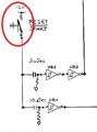
There is a timer that is adjustable from about 25 usec to 125 us for the time the arc is active and for the other half of the cycle allows the discharge capacitors to recharge. (U13) A flip flop to get it to start with a charge cycle and turn on the discharge of the 130 volts to start the arc. Once the arc starts that flip flop is reset and a second one is turned on to discharge the 95 volt capacitors into the probe. After a short delay there is a sample of a window comparator that indicated if the voltage of the arc is above the window (to far away from the work piece) or below the window (to close to the work piece) or in the window - just right.. This is stored in the latches U10 and 18 to be sent to the step motor controller. If the window voltage is to low the arc is turned off so as not to make a short. If ther is no arc the motor is moved in and the process starts again. The rest of the logic is just resets to keep it looping under the various conditions.
Power section attached:
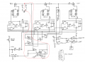
On the left it a FET driver for the 130 volt supply turned on by the discharge 130 from the logic. This signal remains high until an arc is detected by the comparator U8 at the bottom right. It senses the voltage drop across two power diodes. There are other ways to do this but we kind of liked this one.
On the right is another driver to turn on a FET to charge the caps C1. C30 & C31. These are selectable by the operator to set a power level.
In the center is the discharge circuit. It discharges both the 130 volts and the caps into the gap. These supplies are or'ed thru D1 and D2. The gap and electrodes are represented by the neon (U4). This turns out to be an easy way to simulate it because you can change the strike voltage and it's on resistance. I used little isolated dc to dc converters instead of separate charge pumps to keep it simple.
I've seen some warnings about using supplies to do this due to inter-winding capacitance, but these seem to be made for it as the capacitance is only pico farads. Anyone used them for this?
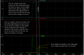
Finally the window comparator. It is operator adjustable with a window about 6 volts wide. Shortbus and I have a disagreement on this. I think it needs to be sampled out in the wave form somewhere (picture attached) and he thinks not. I see a lot of circuits on the net showing the window, but I don't know how it could work without a sample. Maybe there is an EDM guy that could splain it to me.
Also attached is the simulation of the whole thing except for the bulk supplies. I have schematics for them and separate simulations if anyone is interested.
I would really appreciate your input and insights. There are a lot of poor circuits running around so a good one might be something nice to have.
Background:
I have been working with Shortbus on some electronics for his EDM mechanics. We started out trying to make it as fast as possible and with all the bells and whistles of a big boy machine. Needless to say this one got pretty complicated pretty fast so where I ended up was a simpler version that will run (I hope) at about 1000 arcs per second. There are a few constraints that seem to limit this. The first is his transformer is rated at 75 volts RMS at 15 amps - yes a brute. This gave us about 95 volts after rectification and filtering. Since it drives a 40,000 ufd cap I thought it best to follow the recommendations to derate it by 40% so 9 amps or so. The targeted arc current is around 35 amps so this limits the duty cycle.
The second is the use of a stepper motor to drive the ram up and down. The stepper runs in 1/10 microstep mode so my guess is maybe it can do 1000 steps/second from a dead stop. I would appreciate input on this. The first design only delayed the arc when the motor needed to move, but again got complicated, so I decided to let the motor set the duty cycle as it will be safe for the transformer.
If I was convinced that the motor would never have to move two or three times in succession it might be possible to speed this up as well. But if the motor fails to move it would be bad news.
The third bell and whistle that bit the dust was a provision for a delayed arc. That's a case where for whatever reason the arc doesn't start right away. This meant another timer to decide how long to wait for an arc so this case will now just have a shorter burn time.
We left in the option of starting the arc with a higher voltage since he already had the stuff.
How it works. Logic attached.
There is a timer that is adjustable from about 25 usec to 125 us for the time the arc is active and for the other half of the cycle allows the discharge capacitors to recharge. (U13) A flip flop to get it to start with a charge cycle and turn on the discharge of the 130 volts to start the arc. Once the arc starts that flip flop is reset and a second one is turned on to discharge the 95 volt capacitors into the probe. After a short delay there is a sample of a window comparator that indicated if the voltage of the arc is above the window (to far away from the work piece) or below the window (to close to the work piece) or in the window - just right.. This is stored in the latches U10 and 18 to be sent to the step motor controller. If the window voltage is to low the arc is turned off so as not to make a short. If ther is no arc the motor is moved in and the process starts again. The rest of the logic is just resets to keep it looping under the various conditions.
Power section attached:
On the left it a FET driver for the 130 volt supply turned on by the discharge 130 from the logic. This signal remains high until an arc is detected by the comparator U8 at the bottom right. It senses the voltage drop across two power diodes. There are other ways to do this but we kind of liked this one.
On the right is another driver to turn on a FET to charge the caps C1. C30 & C31. These are selectable by the operator to set a power level.
In the center is the discharge circuit. It discharges both the 130 volts and the caps into the gap. These supplies are or'ed thru D1 and D2. The gap and electrodes are represented by the neon (U4). This turns out to be an easy way to simulate it because you can change the strike voltage and it's on resistance. I used little isolated dc to dc converters instead of separate charge pumps to keep it simple.
I've seen some warnings about using supplies to do this due to inter-winding capacitance, but these seem to be made for it as the capacitance is only pico farads. Anyone used them for this?
Finally the window comparator. It is operator adjustable with a window about 6 volts wide. Shortbus and I have a disagreement on this. I think it needs to be sampled out in the wave form somewhere (picture attached) and he thinks not. I see a lot of circuits on the net showing the window, but I don't know how it could work without a sample. Maybe there is an EDM guy that could splain it to me.
Also attached is the simulation of the whole thing except for the bulk supplies. I have schematics for them and separate simulations if anyone is interested.
I would really appreciate your input and insights. There are a lot of poor circuits running around so a good one might be something nice to have.
Attachments
-
26.9 KB Views: 20
-
 107.7 KB Views: 59
 -
 114.9 KB Views: 55
 -
 73.4 KB Views: 45
") Or maybe it was the mention of shortbus?
Or maybe it was the mention of shortbus?