 Facebook
 Google
 GitHub
 Linkedin
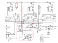
That's true when the switch is at reset, but when it is in start (as shown) it is not at 12 volts or ground, but what I call floating. A little bit of noise would make it look like another reset / start pulse.[/QUOTE][QUOTE="shortbus, post: 869976, member: 6184
@shortbus
In response to your point #1, I thought by using a SPST toggle the line would not be floating but stay at supply (12V) level. I was under the assumption that the S/RS would only cycle once and then stay at the level that results from that.
That double switch symbol was my fault trying to learn Diptrace. Couldn't find a toggle switch but could find a push button. So used a push button then drew the toggle by hand before scanning and posting. Sorry.
My thoughts were to use one switch to do both things, that's why the two different times in the edge detectors. A short one for reset, and a longer one for start. Then both would stay at 12V (no longer detecting an edge) for the duration of the burn, due to switch being a toggle.

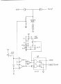

") Worked out an easy way for the timer to disable the comparators for the 90/20. The 339 is an open collector output so it needs a pull up to +12 for the output to go high. But we can also add a diode from the timer output to each comparator output to disable them while the caps charge. The anodes go to the timer and the cathode of each one goes to each comparator. We can discuss how long the timer needs to be later.
Worked out an easy way for the timer to disable the comparators for the 90/20. The 339 is an open collector output so it needs a pull up to +12 for the output to go high. But we can also add a diode from the timer output to each comparator output to disable them while the caps charge. The anodes go to the timer and the cathode of each one goes to each comparator. We can discuss how long the timer needs to be later.


