 Facebook
 Google
 GitHub
 Linkedin
Hi,
I mainly design digital electronics but I had to use a microphone input to a microcontroller which does FFT on the received signal and at the same time reroute the audio to the speaker amplifier as a karaoke feature.
The first prototype is quite noisy. The board is powered by a Meanwell IRM-60-5ST, there is a dedicated LDO for analogue 3.3V and digital 3.3V.
4 layer PCB, dedicated power plane under analogue section and full GND power plane on PCB. Layer 1- signal+components, Layer 2 + power plane, layer 3 GND plane, layer 4 signal
1, I get quite a bit of 50Hz noise on the electronics on its own, but if I connect the scope tip negative to the board negative then it is quite, so if I want to measure it is quite.
2, the speaker amplifier is PAM8019 with added LC low pass filter. Unfortunately I made a mistake that the microphone input is going close to the class D amplifier, and there is no shielding on the top/bottom layer. If I cut the trace from the microphone input to the opamp then it is reasonably quite
3, The PCB is in a big box, there is a cable going from the PCB to the 6.5mm jack, the microphone is a cheap DM-520, its cable is unbalanced 2way, shield + core. I need to handle 2x mic, so I have a RJ45 on PCB, using shielded UTP cable (1m) inside the box (plastic) to the 6.5mm jack. I have to detect microphone plug in as well, thats why I use RJ45, shielded, twister 8 core, enough for audio + detection.
If the microphone is not plugged in then the analogue microphone wire is floating. Is than an issue? I get better result if the 6.5mm jack connects mic line to GND if it is not plugged in.
So I know I need to improve routing, but what else i can do to improve it?
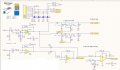
The diagram is an enhanced version with fade in-out, so if no mic is connected I disconnect the preamp from the speaker amp.
I was planning to add a second order high pass filter after the 1st stage, would it be better to have it right at the input? Then the amplifier? Or better to have after the 1st stage?
I was also thinking to remove the second stage for the DSP (bottom right side of the circuit) and have a 80-100 gain on the first stage. Any disadvantage? This is to reuse those opamps as 2nd order filters.
Any other suggestion?
thanks!
I mainly design digital electronics but I had to use a microphone input to a microcontroller which does FFT on the received signal and at the same time reroute the audio to the speaker amplifier as a karaoke feature.
The first prototype is quite noisy. The board is powered by a Meanwell IRM-60-5ST, there is a dedicated LDO for analogue 3.3V and digital 3.3V.
4 layer PCB, dedicated power plane under analogue section and full GND power plane on PCB. Layer 1- signal+components, Layer 2 + power plane, layer 3 GND plane, layer 4 signal
1, I get quite a bit of 50Hz noise on the electronics on its own, but if I connect the scope tip negative to the board negative then it is quite, so if I want to measure it is quite.
2, the speaker amplifier is PAM8019 with added LC low pass filter. Unfortunately I made a mistake that the microphone input is going close to the class D amplifier, and there is no shielding on the top/bottom layer. If I cut the trace from the microphone input to the opamp then it is reasonably quite
3, The PCB is in a big box, there is a cable going from the PCB to the 6.5mm jack, the microphone is a cheap DM-520, its cable is unbalanced 2way, shield + core. I need to handle 2x mic, so I have a RJ45 on PCB, using shielded UTP cable (1m) inside the box (plastic) to the 6.5mm jack. I have to detect microphone plug in as well, thats why I use RJ45, shielded, twister 8 core, enough for audio + detection.
If the microphone is not plugged in then the analogue microphone wire is floating. Is than an issue? I get better result if the 6.5mm jack connects mic line to GND if it is not plugged in.
So I know I need to improve routing, but what else i can do to improve it?
The diagram is an enhanced version with fade in-out, so if no mic is connected I disconnect the preamp from the speaker amp.
I was planning to add a second order high pass filter after the 1st stage, would it be better to have it right at the input? Then the amplifier? Or better to have after the 1st stage?
I was also thinking to remove the second stage for the DSP (bottom right side of the circuit) and have a 80-100 gain on the first stage. Any disadvantage? This is to reuse those opamps as 2nd order filters.
Any other suggestion?
thanks!
Attachments
-
 137.8 KB Views: 10


