Facebook
 Google
 GitHub
 Linkedin
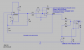
Hi. I need to design a pwm generator circuit using 555 timers with frequency levels up to tens of kHzs or even more. The problem is that I need to adjust both frequency and duty cycle (separately if possible) with a voltage reference and the famous pin 5 (CV) of the timer has caused lots of confusion for me so far. I couldnt find any source explaining quantitatively how does it affect the duty cycle and/or frequency. thats why I decided to give up on that pin and use two 555s with one operating on astable mode as a trigger generator and the other monostable 555 receives these and outputs at the frequency set by the primary timer. I thought changing the frequency and the duty cycle is now separate problems for separate timers and it would be a bit easier to achieve, taking into account the low time of the astable and the pulse width of the monostable one of course. I tried to set some rules in terms of the component values, time parameters, and SR latch characteristics. These may be wrong as they depend only on intuition and some simulations with LTspice with the internal structure of 555 in mind. My efforts has been desperate so far as both freq and d.cycle depend heavily on the component values and the condition to dictate them with source voltage limits the options, with potentiometers excluded as they require mechanical intervention. I would love to hear about any ideas on voltage based control. Thanks
Attachments
-
5.4 KB Views: 25
-
1.8 KB Views: 31