Frequency and duty cycle of LM2596 IC

Thread Starter

xchcui

Joined May 12, 2014
309
LM2596S-Schematic KHz.jpg

Hi.
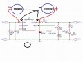
When i put the probes on the 1(Vin)and 2(Vout)pins of the LM2596 IC,as it shown at the photo,i get 300KHz(left photo)and on the other way(right photo)i get 150KHz(as the internal oscillation frequency value should be).
Why do i get 300KHz when i change the probes,instead of 150KHz?
And btw where i should put the probes in order to get the duty cycle(%) value? Thanks.
 
Last edited:

MisterBill2

Joined Jan 23, 2018
27,432
Your measuring device is having a serious effect on the circuit operation. Besides that, neither one of those connections is close to correct for observing frequency or pulse width. In each case the correct measurement will be between the point to be monitored and the system common, which often is "ground". Now you have seen the results of other approaches, which, BTW, do not make sense to me at all.
 

Thread Starter

xchcui

Joined May 12, 2014
309
Normally, the common lead of your test instrument should be connected to the negative lead of the power source.
Your measuring device is having a serious effect on the circuit operation. Besides that, neither one of those connections is close to correct for observing frequency or pulse width. In each case the correct measurement will be between the point to be monitored and the system common, which often is "ground". Now you have seen the results of other approaches, which, BTW, do not make sense to me at all.
LM2596S-Schematic 2.jpg


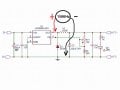
As you may see at the photo:
Positive probe is on the output pin of the chip(2) and the negative probe is at the ground.
(Is this the way,also,to read the duty cycle?)
In this case i got 150KHz,which is probably the frequency of the chip internal oscillation.
But if i reverse the probes,i get 300KHz again,why?
 

MisterBill2

Joined Jan 23, 2018
27,432
The circuit in post #4 shows a much different set of probe connections than the circuit shown in post #1, which is what I addressed in my post #3.
Also, almost every point in a switch-mode supply is able to affect the operation of the circuit. Switchers are a lot more complex than most other circuits.
 

Thread Starter

xchcui

Joined May 12, 2014
309
The circuit in post #4 shows a much different set of probe connections than the circuit shown in post #1, which is what I addressed in my post #3.
Also, almost every point in a switch-mode supply is able to affect the operation of the circuit. Switchers are a lot more complex than most other circuits.
The photo is different since i made some change in it according to your and BillB3857 advice,but anyway you actually haven't answer the questions.
The frequency of this module is 150KHz(datasheet)and when i measure it between the IC output(2)and ground ,i get 150KHz.So it is fine.
But why when i reverse the probes(minus probe on output(2)and plus probe on ground)i got 300KHz(the frequency is doubled).And again,where you need to put the probes in order to measure the duty cycle?
 

Thread Starter

xchcui

Joined May 12, 2014
309
What are you using to read the frequency? Volt meters have a hard time reading the frequency of rectangle waves.
I am using multimeter with frequency(read up to 1MHz)option and it read okay the frequency.The fact is that it showed me exactly the datasheet frequency-150KHz.
But,again, why when i reverse the probes(minus probe on output(2)and plus probe on ground)i got 300KHz(the frequency is doubled).And where you need to put the probes in order to measure the duty cycle?
 

MisterBill2

Joined Jan 23, 2018
27,432
What I see, relative to the original question, is that the waveshape at pin #2 is not a simple square wave, but rather quite different,and that by referencing the frequency counter to a much higher voltage base you are measuring a much different part of the wave that includes some ringing. That ringing portion of the waveform then crosses the unknown counter trigger threshold twice. That is what happens when you change the reference point by biasing the counter input. If the frequency counter and the power supply had shared a common "ground" connection it would have led to a direct short circuit across the IC output.

This clearly verifies that to obtain a correct measurement the correct reference point must be used.
 

Thread Starter

xchcui

Joined May 12, 2014
309
What I see, relative to the original question, is that the waveshape at pin #2 is not a simple square wave, but rather quite different,and that by referencing the frequency counter to a much higher voltage base you are measuring a much different part of the wave that includes some ringing. That ringing portion of the waveform then crosses the unknown counter trigger threshold twice. That is what happens when you change the reference point by biasing the counter input. If the frequency counter and the power supply had shared a common "ground" connection it would have led to a direct short circuit across the IC output.

This clearly verifies that to obtain a correct measurement the correct reference point must be used.
From your explanation,i understand that the ringing is what makes the frequency double,as it triggers the threshold twice.
But what does it mean?does it mean that the correct reference point is as the photo at post #4?and that the duty cycle can be measured as in post #4?
 

Thread Starter

xchcui

Joined May 12, 2014
309
All the purpose of my question was to know where to put the probes on the module in order to measure the frequency and the duty cycle.
That all!
Only,BillB3857,said something related as he adviced to connect the common to the negative lead of the power source.
Besides that,(main question),should the positive probe be connected to the output(pin 2)of the IC?Do these connecting points(ground and pin 2)proper to measure also the duty cycle?
 

LowQCab

Joined Nov 6, 2012
5,101
What You want to measure and see going on requires an Oscilloscope,
a Multimeter, even the expensive ones, will deliver very questionable results in this situation.
.
.
.
 

Thread Starter

xchcui

Joined May 12, 2014
309
What You want to measure and see going on requires an Oscilloscope,
a Multimeter, even the expensive ones, will deliver very questionable results in this situation.
.
.
.
Okay,LowQCab.I agree with you that an Oscilloscope is a better way to measure those parameters.Lets assume that i use an Oscilloscope,where should i connect the probes in order to measure the duty cycle and the frequency?
 

LowQCab

Joined Nov 6, 2012
5,101
Pin-2 to Ground.
This will display both the Duty-Cycle percentage and the Frequency at the same time.
The 2 measurements are inseparable, they are not separate in any way.

What You will be looking at,
aside from the Input-Voltage,
is the Forward-Voltage of the Diode,
or Ground,
or even a small negative spike slightly below Ground.

In reality, some pretty strange behaviors will be on display,
but they are "usually" quite normal and expected.

These things are normally not something that You should need to measure,
or even care much about verifying.
Simply study the Spec-Sheet,
and also look for any "Application-Notes" PDFs that may be available.

Most problems are created in the Filter-Section, or, by way of improper Diode selection.
All three of these parts are critical to obtaining the expected behavior that You want.

"Simulating" the Circuit, with the expected "Modeled-Load" attached FIRST,
will answer a lot of questions before ever touching a Soldering-Iron.
( which will also provide a "simulated" Oscilloscope-Display )

Don't expect greater than ~80% Efficiency without some "cut-and-try" experimentation.

Most people are trying to minimize the size and expense of the Filter-Section-Components,
this will give you headaches for days.
Employ plenty of overkill here to make you life easier.
.
.
.
 

Thread Starter

xchcui

Joined May 12, 2014
309
Pin-2 to Ground.
This will display both the Duty-Cycle percentage and the Frequency at the same time.
The 2 measurements are inseparable, they are not separate in any way.

What You will be looking at,
aside from the Input-Voltage,
is the Forward-Voltage of the Diode,
or Ground,
or even a small negative spike slightly below Ground.

In reality, some pretty strange behaviors will be on display,
but they are "usually" quite normal and expected.

These things are normally not something that You should need to measure,
or even care much about verifying.
Simply study the Spec-Sheet,
and also look for any "Application-Notes" PDFs that may be available.

Most problems are created in the Filter-Section, or, by way of improper Diode selection.
All three of these parts are critical to obtaining the expected behavior that You want.

"Simulating" the Circuit, with the expected "Modeled-Load" attached FIRST,
will answer a lot of questions before ever touching a Soldering-Iron.
( which will also provide a "simulated" Oscilloscope-Display )

Don't expect greater than ~80% Efficiency without some "cut-and-try" experimentation.

Most people are trying to minimize the size and expense of the Filter-Section-Components,
this will give you headaches for days.
Employ plenty of overkill here to make you life easier.
.
.
.
Thanks,LowQCab for your answer.I think i got the idea.
Thank you all.:)
 
Top