Dual power

Thread Starter

Giuseppe33

Joined Jan 18, 2022
5
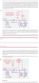
Hello I'm trying to make a circuit that utilizes two sources of power (3.5volts per power source). Is there a way I can accomplish this without any circuit boards, prevent any back feed that can cause the battery to charge if they are both connected and having one as a primary but if disconnect will rely on the other power source?
 

BobTPH

Joined Jun 5, 2013
8,961
Why not give us specifics? Making a question as general as possible does not get the best answers.

What are these two 3.5V sources? I know of no battery that produces 3.5V.

And how much current sre we talking about?

Bob
 

LesJones

Joined Jan 8, 2017
4,190
You have not answered Bob's question very clearly. Am I correct in understanding that you have an external 3.5 volt power source that may fail and an onboard 3.5 volt battery and the load requires exactly 3.5 volts. What is the onboard battery technology ? I do not know of any battery technology that gives exactly 3.5 volt. How much current does the load require ?

Les.
 

k1ng 1337

Joined Sep 11, 2020
960
Don't expect a reliable reply without posting your plan and a schematic.

In leu of that, two diodes, one coming from each power source will serve as a crude "backup power supply" and will prevent one supply from powering the other. This method is in the Pi Pico's datasheet. You circuit may not be designed for this however..
 

Attachments

Papabravo

Joined Feb 24, 2006
21,225
In general the answer is yes, but it doesn't come without a cost. In this case the details mentioned by other posters are relevant and essential to an appropriate answer.
 

ThePanMan

Joined Mar 13, 2020
793
As you know, the CR 123 is not a rechargeable battery. IF you build a device to take over the task when battery voltage drops below a set point you must have a way to isolate the battery from the external charging (or powering) source. Usually a blocking diode will work. However, a diode will also drop some voltage. Depending on which type of diode you choose you can drop about half a volt.

Tell us about the second power source you're thinking about. If it's a pocket battery pack that can be plugged in then using a barrel connector and socket, you can get a socket that can switch off the internal battery. But like BobTPH said; just keep extra batteries on hand. When the batteries get too low - just change them. That's about the best way to have something "Without" a circuit or circuit board possible.
 

k1ng 1337

Joined Sep 11, 2020
960
In a scenario that the battery does get too low a automatic backup would be ideal.
How do you expect to achieve this without any circuitry? Or are you thinking of some kind of "plug and play" battery pack/power bank?

What is model of your device? I suspect any crude modification to a sensitive device would be in poor taste and prone to failure due to it's spectral nature not to mention it's strapped to your face haha.
 

DC_Kid

Joined Feb 25, 2008
1,072
Two Li ION 3.7v batts, where one batt holds a small low amp relay open for itself, and if the batt falls off or dies the relay moves to another throw location bringing the 2nd batt onto Vcc.

Is the goal like a UPS or something? Does the rise time for 2nd batt need to be sub msec fast?
 

crutschow

Joined Mar 14, 2008
34,439
prevent any back feed that can cause the battery to charge if they are both connected and having one as a primary but if disconnect will rely on the other power source?
Those two requirements are somewhat mutually exclusive.
How would you designate which battery is "primary".

As diodes (even Schottky types) may generate too large a voltage drop for your isolation requirements, you could use an "Ideal diode" circuit with MOSFETs but those are more complex to implement.
Below is the LTspice simulation of an example circuit:
It uses a low-voltage, low-power rail-rail op amp to sense which battery has the higher voltage and switches the P-MOSFET gates accordingly (low gate voltage turns the MOSFET on). This works because MOSFETs conduct equally well in either direction when ON.

Note that the output (yellow trace) always equals the battery with the highest voltage (minus the small drop due to the MOSFET on-resistance), and there is no current feedback between the two batteries.

The P-MOSFET must be a logic-level type with the maximum Vgs(th) no more than 2V.

1642532791850.png
 
Top