Driving peltier with PWM pulse from Raspberry pi

Thread Starter

meena udayasankar 1

Joined Apr 10, 2017
19
Hi all,

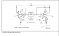
I am trying to drive the TEC12706 peltier with 12V input.
PWM pulse will be given from Raspberry board(python code) with 1kHz frequency and 50% duty cycle.
Low pass filter I have designed is 500Hz.
I tested the circuit. The peltier is working fine but I am not getting the correct duty cycle. The duty cycle across the peltier should be 6V. but i am getting as same 12V.
p(+ve) and p(-ve) is connected to peltier

can anyone give some idea? where i am making mistake? I can't able to proceed my project now. I am stuckked with this.

Any idea. plz share. thanks
.

upload_2017-7-1_18-13-23.png
 

Marcus2012

Joined Feb 22, 2015
425
Hello

Afaik Peltier elements do not work that well with PWM. PWM seems to induce higher Ohmic losses in the peltier module and the 12706 is rated to run at DC. If you need to control it with a Pi then I would suggest temp monitoring and use relays to switch it directly on and off depending on temp range.
 
PWM pulse will be given from Raspberry board(python code) with 1kHz frequency and 50% duty cycle.
Low pass filter I have designed is 500Hz.
I tested the circuit. The peltier is working fine but I am not getting the correct duty cycle. The duty cycle across the peltier should be 6V. but i am getting as same 12V.
Duty cycle is measured in %.

Unless you have a TRMS AC meter, you won;t read 6V for a 50% duty cycle. The frequency response of your meter may not be able to see 500 Hz.

the base resistor R would need to be: (5-2.5)/0.025 ASSUMING a 5V and Vbe of 2.5 V

The transistor is probably a bad choice, SOA wise, A logic FET should be a much better choice.

Without an H-bridge you can either heat or cool, not both.
Vbe is 2.5 V so, (5-2.5)/25 mA

Tray an incandescent light bulb or a LED and resistor for a load.

DATASHEET - peltier http://www.google.com/url?sa=t&rct=...sh.PDF&usg=AFQjCNHWDjvI2wbFE7MdfZ742YHyVcoNLQ

DATASHEET TIP122 - https://www.google.com/url?sa=t&rct...-D.PDF&usg=AFQjCNFWaUtXrrOTKyLrpyJ_ZyNSaFPfxw
 

Thread Starter

meena udayasankar 1

Joined Apr 10, 2017
19
How are you measuring voltage? A standard DMM won't give a reliable reading with PWM.
If you want a smoothe voltage on the capacitor it needs to have a much higher capacitance.
I was checking the response of the peltier in CRO only where I got the maximum pulse amplitude of 12V and minimum is 9.87V.
I was bit confused with this.
 

crutschow

Joined Mar 14, 2008
38,316
What is the purpose of the filter at the input to the transistor?
If you are trying to average the PWM signal to get a DC out. that circuit won't work for that.
Calculate the current into the transistor base with a 50% duty-cycle. You will likely find that it is sufficient to fully turn on the transistor, as you measured (I assume the 12V you measured is across the Peltier).
There's only a very narrow range of PWM duty-cycles that will place the transistor in its active region (depending upon its gain).

If you want the PWM to across the Peltier then you don't want the filter.

So what signal do you want to appear across the Peltier -- the PWM directly, or the DC average of the PWM voltage?
 

shteii01

Joined Feb 19, 2010
4,644
Hello

Afaik Peltier elements do not work that well with PWM. PWM seems to induce higher Ohmic losses in the peltier module and the 12706 is rated to run at DC. If you need to control it with a Pi then I would suggest temp monitoring and use relays to switch it directly on and off depending on temp range.
One trick is to use pwm to generate desired "dc" voltage. Maybe that is what they are doing.
 

BobTPH

Joined Jun 5, 2013
11,463
That is what he is trying to do, but that is not what his circuit is doing. It is putting the average voltage on the base of the transistor. This will be enough the turn the transistor on for all but very low duty cycles.

(Just restating what Crutschow has already said.)

You could make it approximate that by simply using the transistor in an emitter follower configuration instead of common emitter.

Bob
 

Marcus2012

Joined Feb 22, 2015
425
PWM vs. Direct Current

Not sure if there is any bias in the argument or how it may apply to your TEC as I don't know your application. But if you drive the TEC with PWM you will decrease the heat your can transfer across the module as you are increasing losses from joule heating (I^2*R)
 

Thread Starter

meena udayasankar 1

Joined Apr 10, 2017
19
Thanks a lot for all. I don't have much experience in the peltier. your answers helped me a lot.

I removed the LPF filter in front of transistor and directly gave the PWM pulse of 1khz with 50%duty cycle and driven the peltier with 5V.

Peltier is working and getting heated up. I checked the Voltage across the peltier in DSO. I am getting 3.2V max and 3.02V min.

If I give 7V, the output in DSO is 4.5V in range. As I keep on increasing the input voltage to peltier, the output across the peltier is increasing.

I don't know how i can related it with my 50% duty cycle PWM pulse..

I have to heat the peltier to from 30 to 100 deg celsius and once it reach 100 deg , peltier should cool fast.

In order to cool the peltier, I have to interchange the input supply (i.e, vin and gnd).

To monitor the temperature, using thermocouple with Max3185J board. Once the python code reads 100 deg celsius I have to cool the peltier.
How this condition is possible with PWM pulse? though i setted the PWM duty cycle to 0%, the peltier is not cooling fast, it's still in heating mode because of its 5V input .

Any idea. Please share.
Thanks in advance
 

MrChips

Joined Oct 2, 2009
34,628
Thanks a lot for all. I don't have much experience in the peltier. your answers helped me a lot.

I removed the LPF filter in front of transistor and directly gave the PWM pulse of 1khz with 50%duty cycle and driven the peltier with 5V.

Peltier is working and getting heated up. I checked the Voltage across the peltier in DSO. I am getting 3.2V max and 3.02V min.

If I give 7V, the output in DSO is 4.5V in range. As I keep on increasing the input voltage to peltier, the output across the peltier is increasing.

I don't know how i can related it with my 50% duty cycle PWM pulse..

I have to heat the peltier to from 30 to 100 deg celsius and once it reach 100 deg , peltier should cool fast.

In order to cool the peltier, I have to interchange the input supply (i.e, vin and gnd).

To monitor the temperature, using thermocouple with Max3185J board. Once the python code reads 100 deg celsius I have to cool the peltier.
How this condition is possible with PWM pulse? though i setted the PWM duty cycle to 0%, the peltier is not cooling fast, it's still in heating mode because of its 5V input .

Any idea. Please share.
Thanks in advance
To cool the TEC you have to reverse the current. You can do this using an H-bridge driver.
Make sure you have a way to remove the heat on the opposite side of the TEC.
 

Thread Starter

meena udayasankar 1

Joined Apr 10, 2017
19
To cool the TEC you have to reverse the current. You can do this using an H-bridge driver.
Make sure you have a way to remove the heat on the opposite side of the TEC.
Ok. H-Bridge is one of the option. Thanks.

Is there any other way to control it PWM pulse or using two transistor?

If my question is wrong, forgive me. It
 

Thread Starter

meena udayasankar 1

Joined Apr 10, 2017
19
To cool the TEC you have to reverse the current. You can do this using an H-bridge driver.
Make sure you have a way to remove the heat on the opposite side of the TEC.
I got the below circuit form Ti. They gave this recommended circuit for thermoelectric coolers. since this peltier draws max 6A, we can set the current limit using this opa569.

Bit confused. To connect the peltier, some people are using amplifier circuit, transistor , voltage follower, etc.
I want to know which one give efficient results.

In the below circuit why 2 voltage follower connected and what is that V set in the second amplifier?

upload_2017-7-6_17-23-44.png
 

Attachments

MrChips

Joined Oct 2, 2009
34,628
A half-bridge is basically two transistors stacked one on top of the other, sometimes called a totem pole.
The output can be either Vcc or GND.

That is what one op amp is doing.

An H-bridge is two half-bridge circuits, sometimes referred to as push-pull. When one half-bridge is pushing, the other half-bridge is pulling.
In this manner you can reverse the current and hence choose to heat or cool the TEC.

The two op amps are doing the same thing.
The OPA569 is overkill. I would choose L298 H-bridge.
 

crutschow

Joined Mar 14, 2008
38,316
The L298 bridge will only carry 2A max.
The TEC12706 operates at up to 6A.

You could use a MOSFET bridge.
Below is the LTspice simulation of a simple bridge circuit that should work.
One input generates current in one direction through the TEC and the other input in the other direction.

The N and P MOSFETs can be any rated at ≥20V Vds and ≤25mΩ on-resistance.
The N-MOSFETs must be logic level type devices.

V2 and V3 are the Raspberry's outputs.

Note that you must make sure V2 and V3 are never on at the same time or you will short the bridge.

upload_2017-7-6_9-6-51.png
 

Attachments

Last edited:

Marcus2012

Joined Feb 22, 2015
425
I have to heat the peltier to from 30 to 100 deg celsius and once it reach 100 deg , peltier should cool fast.

In order to cool the peltier, I have to interchange the input supply (i.e, vin and gnd).
Can I ask what you are cooling and/or heating with this TEC? A 100 Degree hot side temperature seems a little high, how are you dissipating this heat?
 
Top