Driving a LED with a CD4066 and a ramp generator

sghioto

Joined Dec 31, 2017
8,664
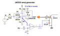
Another analog circuit using a LM358 op amp driving the LEDs on the high side.
In this version when the ramp is activated the output voltage starts at appx 2 volts because C1 is charged initially by the voltage divider of R4 and R5.
This is typically just below the threshold of illumination for most white LEDs.
The LEDs will begin to illuminate almost immediately when the ramp is activated which is the design goal.
C1 and R3 determine the ramp duration
Power ON delay not needed
1757470018484.png
 
Last edited:

sghioto

Joined Dec 31, 2017
8,664
Personally I got better results with the circuit in post #22, IMHO when tested.
Seemingly better control over the LED illumination
Of course it's your project and whatever works for you is best.
:)
 

AnalogKid

Joined Aug 1, 2013
12,174
In circuit #17, Q1 needs a gain of 350. A 2N2222 can't do that.

In the #22 circuit, there might not be enough room in a 5 V circuit for the LED Vf, the Q1 Vbe, and the LM358 output headroom. If there is, the LED current will be lower than expected.

If the voltage across C1 is at its minimum value of 1.8 V, , that is 1.8 V at the Q2 emitter. With "normal" LED Vf of 2 V, that's a problem.


Or am I missing something - ?

ak
 

sghioto

Joined Dec 31, 2017
8,664
In the #22 circuit, there might not be enough room in a 5 V circuit for the LED Vf, the Q1 Vbe, and the LM358 output headroom. If there is, the LED current will be lower than expected.
Depends on the actual LEDs being used. The white LEDs I tested were 10ma at 3 volts, however
I went back and read this statement from the TS:
"have made new tests : under 5 V a warm white LED draws 10 mA with a 100 Ohms resistor."
That = 4 volts across the LED so correct a LM358 will not work at 5 volts but a MCP602 will.

The TS prefers to use the circuit in post #17.
My measurements with a 2N2222A with a 50ma load show a collector voltage of 0.13V using a 10K base resistor with the max output from the LM358 at 3.7V.
The base voltage at 0.78V leaves 2.91V across the 10K resistor or 291uA of base current.
Gain = .050/.000291 = 172.
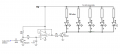
So after all is said and done I offer a third version with minimum parts:
With R4 at 5.1K drops the collector voltage to 0.1V
1757548013005.png
 
Last edited:
Top