Facebook
 Google
 GitHub
 Linkedin
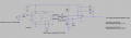
Oh right. I removed the "smoothing capacitor" and increased C2 to 100nF. Works great in the simulation.
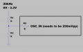
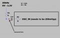
The signal is 2V peak to peak measured with the capacitors for the resonance. Which I think is right to take into account, right ?
The signal is 2V peak to peak measured with the capacitors for the resonance. Which I think is right to take into account, right ?
Last edited: