Yes.
The reason I suggested the inverter is that it would make it easier at a later date to gate the signal on and off. If you don’t need to do that he 1402 makes perfect sense.
You thought about eliminating the multiplexer by using different frequencies. Since I use the 20kHz generated by the counter I thought I could use the 40kHz and 80kHz. Is that practical ? or is there a better way ?
That might be problematic. The harmonics from a squarewave should all be odd, so you would get 60kHz, 100kHz etc from your 20kHz, but I wouldn’t completely rule out any even harmonics, then the 20kHz coil is producing 40kHz and 80kHz. I honestly don’t know if it would cause problems or not.
i think 20kHz * cube root of two and 20kHz/cube root of two would Avoid that problem, but maybe as the frequencies are closer together, cause others. You will only find out by experimentation.
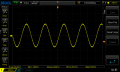
Another problem I still have is that I don't get the DC output. I checked the opamp three times but the output is a sine wave that changes the amplitude as the distance changes. I measured the output of the mixer without the opamp attached and then with the opamp attached.
What could be the problem ?
If the signal gets to 5V too fast (I don't get accurate readings when the receiver is very close to the transmitter). Do I just need to make the amplification smaller ?
And then also, could I use a full bridge rectifier to get the dc analog signal ? I could imagine that this way I can read the whole range.
If the signal gets to 5V too fast (I don't get accurate readings when the receiver is very close to the transmitter). Do I just need to make the amplification smaller ?
Yes, but:
1) you lose the mixer’s ability to eliminate interfering signals.
2) it stops working entirely when the signal is less than the forward voltage drop of the diodes in the bridge.
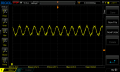
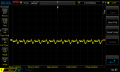
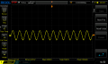
Something bugs me. I measured the output of the mixer, while changing the local oscillator (at a distance of about 20cm from the transmitter). First I fed the LO signal with a 100nF capacitor in series into the OSC_B pin of the mixer and then without the capacitor. When I used no capacitor the measured output is much cleaner than with a cap.
I did read
the external signal can be injected at OSC_B (pin 6) through a DC blocking capacitor
A pretty waveform is not the objective here. What you are looking for is a DC level that shifts with the distance from the receiver. The only signal should be double the transmitter frequency.
it may take some experimentation, including with the level of the oscillator signal.
Yeah but what I was thinking is, if I can see a much bigger change (between those two setups) on the oscilloscope it would maybe be worth to use the full bridge rectifier, since the voltage drop across the diodes would be insignificant compared to the signal strength. Or I can just amplify the signal to make the diodes worth.
Remember that the double balanced mixer isn't simply a preamp. The output should be a dc level (which represents the signal level) with perhaps a 40kHz signal superimposed on it, which may be filtered out. What there shouldn't be is any remaining 20kHz.
Or you can use a preamp, with a schottky diode bridge; or a voltage doubler - both of which need enough received signal to exceed the diode forward voltage drop in order to work.
And there is the alternative of the precision rectifier; but if you're going to use a good about of analogue signal processing, you would be better off with a bigger supply voltage, and + and - rails. In real terms, the difference between diode voltage drop and full supply of +/-2.5V doesn't give you enough dynamic range.
Neither of the "preamp" solutions filters out unwanted signals (though a resonant receiver circuit will help).
I also came across this application note which looks interesting. http://www.farnell.com/datasheets/1760794.pdf
The RSSI output is in dB. Whilst it is almost impossible to have an output that varies linearly with distance, logarithmically is better than 1/x^2.
The circuit needs only a single supply (I bet 5V would work, although it says 6V), and I bet you could leave off the LM358 and one of the filters if you're going into the A/D of a microcontroller.
Because it's made from a radio IC, the fact that 20kHz is at the limits of "audio" won't be a problem.
I will definitely look into this later. At the moment I'm waiting for a pcb I designed. I simulated the transmitter design and found that my realisation of the circuit isn't near the voltage levels I should get. I feel like those analog things can't be done real good on breadboards with (a lot) jumper cables. I also got myself a proper 1 ohms resistor.
I just want to make sure I get a good transmitter signal before optimising the reciever. I hope the pcb will do that. Unfortunately ordering always takes a while -.-
But I will report my findings for sure once I got everything up and running.
Alright, so I did some testing with the transmitter. I think I got an acceptable transmitter now. Anyways I still haven't figured out the receiver. I found the SA612 as a LTSpice model and attached the opamp configuration as you suggested on page 4 of this thread.
For the simulation: white is the mixer output, green is the opamp output with respect to ground, blue is the signal between pin 1 and 2 of the mixer, and red is the oscillator input on pin 6. But the problem is that the opamp output is going down to 0.
What's the problem ?
EDIT: the opamp in the simulation is a generic one from LTSpice.
EDIT2: I think I don't need that much amplification anymore. But I can't get the signal to be DC.
Looking good to me - I think that the only problem is too big a signal or too much gain.
Check the following:
1) If V2 =0 the output should settle in the centre of the supply (2.5V)
2) Increase V2 slowly, and the output should move up or down
3) Change the phase of V2 and the output should go the other way
4) Change the frequency of V2 (leaving V1 alone) and the output should be 2.5V
Ok, so I checked what you suggested and it's working right. I checked the maximum signal that gets into pin 1 and 2 and that is 2Vpp. I adjusted the resistors of the opamp configuration so that 2Vpp would be as close to 0V as possible and when I change the phase I get as close to 5V as possible. I attached the configuration. Does that look reasonable ?
I still don't quite understand the opamp circuitry. I just tried different resistor values and got something working now. My understanding is that the gain of the circuit is 2 now, because R5 is twice as big as R1. I also added a smoothing capacitor to the output.
Yes, but not the "smoothing capacitor". Op-amps really don't like capacitors on their outputs! Increase the 10n instead.
Correct, gain is 2.
I wonder if the signal on pins 1 and 2 is quite as high as 2V p/p. Do you really get that much out of your receiver coil?
 Facebook
 Google
 GitHub
 Linkedin