Driving a 3D coil with the AD9833

Status
Not open for further replies.

Ian0

Joined Aug 7, 2020
13,158
A bit elaborate and a gain of 500 seems a lot, especially with no frequency filtering. Once the output gets to maximum, you can no longer judge the distance!
You can achieve something good enough with a cheap op-amp like an MCP6021.
Well I was expecting a linear output voltage, but that won't happen I guess.

I would like to try to amplify the coil output.
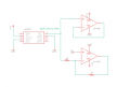
So I found another project of the authors with a similar goal. They even open sourced their circuits. One of those circuits is the receiver (here is the other part for the receiver). They are still using a rectifier, but could the opamp configuration as they use it apply to me ?

thanks,
8
That IS an instrumentation amplifier.
A gain of 500 seems a lot, especially with no frequency filtering. Once the output gets to maximum, you can no longer judge the distance! (But the SA612 has gain)
You can achieve something good enough with a cheap op-amp like an MCP6021, in a standard amplifier circuit. One end of the coil can be earthed, and you only need use one input of the SA612
 

Ian0

Joined Aug 7, 2020
13,158
I found this video where they used the same kind of coil. And at some point in the video one can see that they push around 320mA through the coils at a frequency of around 30kHz. They also say that they power the transmitter from a regular 5V usb power supply. They also have a medium range demo of their stuff and a long range demo. So I feel like the transmitter must get stronger.

How do they get that much current ?
Maybe a series resonant circuit (but hard to control), or maybe a stepped up power supply.
5V supplies can be a bit restrictive. +/-12V might be a lot easier to work with. Single-ended power supplies tend to require lots of extra bits to bias inputs to the centre.
 

Ian0

Joined Aug 7, 2020
13,158
And then lets say we can't get anymore out of the receiver easily. Could I just crank up the voltage (maybe 9V or 12V) on the transmitter to ease the pickup ?
The coils will have a maximum current rating. If they are ferrite-cored it will be due to the ferrite saturating. If they are air-cored then it is simply due to the maximum operating temperature.
 

Thread Starter

8dm7bz

Joined Jul 21, 2020
199
Alright so I guess let's not focus on their circuits :)
So I tried to build a resonant circuit with this coil. I used the z winding which is at 1.39mH which would result in 174.6 ohms at 20kHz. I put a 47nF cap with a 20 ohms resistor in series. I calculated the voltage across the inductor to be 45.5 V at resonance. For the Q factor I get 9.1 and the bandwidth is 2.2 kHz. This setup would result in around 250 mA through the circuit.
But when I measure the voltage across the inductor it's not even close to 45.5 V. Are my calculations wrong, or is it the loose wiring I have ?

Any way I get quite better results on the pickup, even without the differential opamp.

thanks,
8
 

Attachments

Ian0

Joined Aug 7, 2020
13,158
What is the resistance of the coil?
Don’t forget you have only 2.5V ac, so the best you could expect if the coil had zero resistance would be 125mA. With that inductance it would be 22V across the coil.
 

Thread Starter

8dm7bz

Joined Jul 21, 2020
199
Could you elaborate a bit more please. The resistance of the coil is 2.9 ohms. I don't understand why I only have 2.5 ac ?

I was doing it like the example number 1 on this page. But it assumes a sinusoidal 9V input. Doesn't that mean 9V peak to peak ? And is there a difference between a sinusoidal input wave and a square input wave ?
 

Thread Starter

8dm7bz

Joined Jul 21, 2020
199
oh ok, got it.

so would it work to first step up the 5V to 10V and then drive the resonant circuit with it. That way I could get 250 mA, right ?
 

Ian0

Joined Aug 7, 2020
13,158
Yes, but you could also double the voltage by driving both ends of the coil with the 20kHz squarewave, but inverting the drive to one end. So then you have +/- 5V across the coil instead of +/- 2.5V.
Beyond that, you would have to step up the supply voltage.
 

Thread Starter

8dm7bz

Joined Jul 21, 2020
199
oh now I get what you said before. That is a brilliant idea. I will try that with the AD8615 in an inverting amplifier at unity gain, since that is what I already have. thanks, I already forgot about that
 

Thread Starter

8dm7bz

Joined Jul 21, 2020
199
Ok, so I tried doing it without the 74HC04 but ended up frying 3 out of my 5 opamps. I will get the 74HC04 probably next week.
But I don't understand how I would get the -5V with that. Does it invert the +5V to -5V ? Or how would the wiring be ?
 

Thread Starter

8dm7bz

Joined Jul 21, 2020
199
Thanks bertus for the article. I understand now that the bridge amplifier works by applying a negative voltage to one of the opamps by putting the 5V to the v- and the 0V to v+ of the opamp. Is that right ? And if so, would I supply the 74HC04 with +5V on pin 7 (GND) and 0V on pin 14 (VCC) ?

thanks,
8
 

Ian0

Joined Aug 7, 2020
13,158
erm. . . No - if you wire it up backwards it will short out the power supply. Don't do that.

So you have a 20kHz squarewave, going from 0V to +5V. Then you invert it with the 74HC04, so you have another 20kHz squarewave going from 0V to +5V, but this one is 0V when the other one is +5V and vice versa.
You have the same voltages across the coil (because the MCP*** is just a buffer).
So if you put your meter across the coil, (red lead at left end, black lead at the right end) , for one half of the cycle, the left hand end is at +5V and the right hand end is at 0V, and your meter will read +5V. For the other half of the cycle, the left hand end is at 0V and the right hand end is at +5V, so your meter will read -5V.

In the previous situation the capacitor fixes the right hand end to +2.5V, so for the first part of the cycle the left hand end is at +5V and the right hand end is at +2.5V, so the voltage across the coil is +2.5V.
For the second part of the cycle, the left hand end is at 0V and the right hand end is at +2.5V, so the voltage across the coil is -2.5V.
 

Thread Starter

8dm7bz

Joined Jul 21, 2020
199
Ok I think I understand, maybe not. I attached an opamp configuration and would like to know what's wrong with it (if there is something wrong with it). I think it would give me 10Vpp at the output.

And then I put the dual MCP*** configuration together. Is that wired correctly ?

thanks,
8
 

Attachments

Ian0

Joined Aug 7, 2020
13,158
You have vdd and vss reversed on the lower op amp, and the non-inverting input needs to be biassed to halfway (2.5V) - equal value resistors to V+ and gnd.
Also, op-amps don't do squarewaves very well. Look at the slew-rate.
 

Thread Starter

8dm7bz

Joined Jul 21, 2020
199
I reversed the vdd and vss on purpose. I thought that would give me a 0V and -5V rail. But I guess that's not how it works. thanks
 

Ian0

Joined Aug 7, 2020
13,158
1) The people who designed the IC put lots of diodes in it to protect the inputs and outputs. Those diodes have their cathodes connected to Vdd and anodes to Vss, so if you connect Vss to a higher voltage than Vdd, it's the same as connecting a diode across your power supply.
2) you don't have a -5V rail, you only have +5V and 0V.
 

Thread Starter

8dm7bz

Joined Jul 21, 2020
199
Alright so the inverter came in today and I tried hooking everything up. Works great, I get the 10Vpp now. But I can't get the 40kHz reproduced. The output of the mixer is not a 40kHz wave anymore as it was before. What could I have connected wrong ?
 
Status
Not open for further replies.
Top