Driving a 3D coil with the AD9833

Thread Starter

8dm7bz

Joined Jul 21, 2020
199
Sorry, I didn't mention anything really.
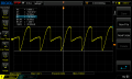
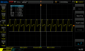
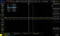
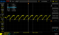
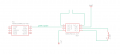
I attached the current receiver setup, and the coil I use is this one. In particular I use the z winding (7.3mH). For the output level, it would be the strongest signal I could get I guess.

I understand that I should bring the circuit to resonance, but I don't quite understand where two put the capacitors. I calculated them to be around 8.67nF and placed two 10nF caps in series with IN_A/IN_B and the coil. Is that right ? It helps at least to make the signal cleaner.
 

Attachments

Last edited:

Thread Starter

8dm7bz

Joined Jul 21, 2020
199
Oh and then also for the two mosfet driver. Is there an easy way to invert one signal. Could that be done with an opamp at unity gain ?
 

Ian0

Joined Aug 7, 2020
9,684
Resonant capacitor goes across the receiver coil. Parallel resonant = infinite impedance at resonance = maximum voltage . Series resonant = zero impedance at resonance = maximum current.
2 x 10n in series is 5n - you probably need it closer. First measure it to see if it really is 7.3mH. Start with 3.3n+3.3n+1n+1n and add or subtract 1n to get the best signal.

Yes, but the 74HC04 is easier!
 

Thread Starter

8dm7bz

Joined Jul 21, 2020
199
I measured it, and it's about 7.3mH, and I got the best results with a 47nF and a 10nF in series (across the coil). Which would result in 8.2nF. I attached a picture to describe my current situation.

At the moment I can see a voltage change on my oscilloscope up until around 50cm between the transmitter and the receiver. So what do I do next to strengthen the pickup ? I read something about an instrumentation op amp. Does that work ?
 

Attachments

Ian0

Joined Aug 7, 2020
9,684
I think you might have too much oscillator signal
If the required LO is beyond oscillation limits, or the system calls for an external LO, the external signal can be injected at OSC_B (pin 6) through a DC blocking capacitor. External LO should be 200 mV (peak-to-peak) minimum up to 300 mV (peak-to-peak) maximum.
So, divide your 20kHz signal by 20-ish and connect it to pin 6 through a capacitor.
How much range are you aiming for?
 

Thread Starter

8dm7bz

Joined Jul 21, 2020
199
Great, I know get a cleaner signal. Now I feed a 240mV peak to peak oscillator into pin 6. Works great, thank you.

My aim is to get as close to 1 metre as possible. at minimum I would like to get 80cm. About an arms range.
 

Attachments

Ian0

Joined Aug 7, 2020
9,684
So, you've got a 40kHz signal. Gilbert cell is a multiplier. So output is: sin A sin B = 0.5 cos(A − B) − 0.5 cos(A + B) (from your school trigonometry)
A and B are both 20kHz, so your 40kHz is cos(A+B) and your other product has a frequency of zero - yes - it's DC and the level should be proportional to your signal.
So, you need to extract the DC and remove the 40kHz.
Not quite the instrumentation amplifier you mentioned, but a differential amplifier, incorporating a low-pass filter. You need an opamp with good DC offset, but Doesn’t really Need much high frequency response, like an OP07, or I think there is a low power one called TLV07.
Gain of 10 for a first guess. Input resistors 10k (so not to load the 1.5k output impedance too much) and a roll of at 150Hz.
The second of the two 100k feedback resistors is split into 2, each twice the value, so they look like 100k, but bias the output to half supply.
With no signal you should get 2.5V out. The voltage will go up or down depending on the orientation of the coil, and the amount by which it changes should be proportional to the distance.
This is when you will begin to see if it all has enough gain etc.!

(Instrumentation amp circuit included for reference, you can see it has a much higher input impedance, and you only need to vary one resistor to set the gain.)
 

Attachments

Last edited:

Thread Starter

8dm7bz

Joined Jul 21, 2020
199
Ok, I will build the circuit later this day. Thanks for the drawing.

But would you say that 1 metre is (maybe even easily) possible ?
 

Ian0

Joined Aug 7, 2020
9,684
If we can get a 60kHz signal from Anthorn, Cumbria 190 miles away, I should damn well hope so! (the "Rugby" clock, which is no longer in Rugby)
I know that their transmitter is 17kW, but it's 304000 times further away.
 

Thread Starter

8dm7bz

Joined Jul 21, 2020
199
Alright so, I build the circuit and double checked to make sure I made the right connections. It works great up until roughly 40cm. After that mark the change in voltage becomes quite small. At 40cm I get around 2.56V and at 50cm I get around 2.55V :/

What resistor do I need to change to amplifier more ?
 

Attachments

Ian0

Joined Aug 7, 2020
9,684
Make the 100k bigger (and the 200k to match).
How biG is the signal at the closest point at which it will be used?
Aim for that being an output of 5V or 0V.
You may need amplification between coil and Sa612.
 

Thread Starter

8dm7bz

Joined Jul 21, 2020
199
so I changed the 100k to be 200k and the 200k to be 400k. Didn't really do much. The signal is at 5V when it is really close to the transmitter.
What amplifier configuration would I use for the coil amplification ?
 

Attachments

Thread Starter

8dm7bz

Joined Jul 21, 2020
199
ok, so one thing I changed, which made things a little better is I took the old coil and replaced it with the lower inductance one. Since I now have the mosfet driver, we could output the current it needs I think. It works better anyways.

But it's still not very good
 

Ian0

Joined Aug 7, 2020
9,684
I think a ferrite cored coil should be best. That's what you would use on a long-wave radio.
What were you expecting? A nice linear output voltage proportional to distance? Unfortunately, the output amplitude is proportional to 1/distance squared.
Theory has got you this far. Now time for optimisation.
If you need more gain, you can use a simple non-inverting amplifier stage provided you use a fast-ish op-amp. It's at the top end of the audio range, so nothing particularly special is required, but a 741 won't do. You need 20kHz bandwidth, so the gain-bandwidth product should be more than 20000 x gain.
 

Thread Starter

8dm7bz

Joined Jul 21, 2020
199
Well I was expecting a linear output voltage, but that won't happen I guess.

I would like to try to amplify the coil output.
So I found another project of the authors with a similar goal. They even open sourced their circuits. One of those circuits is the receiver (here is the other part for the receiver). They are still using a rectifier, but could the opamp configuration as they use it apply to me ?

thanks,
8
 

Thread Starter

8dm7bz

Joined Jul 21, 2020
199
And then lets say we can't get anymore out of the receiver easily. Could I just crank up the voltage (maybe 9V or 12V) on the transmitter to ease the pickup ?
 

Thread Starter

8dm7bz

Joined Jul 21, 2020
199
I found this video where they used the same kind of coil. And at some point in the video one can see that they push around 320mA through the coils at a frequency of around 30kHz. They also say that they power the transmitter from a regular 5V usb power supply. They also have a medium range demo of their stuff and a long range demo. So I feel like the transmitter must get stronger.

How do they get that much current ?
 

Attachments

Top