 Facebook
 Google
 GitHub
 Linkedin
Hello everyone, I am new to the site and I'm not in any way an Electrician of any kind. I do a lot of electrical projects that are simple and straightforward to advance my hobbies. The project I am currently on will seem quite elementary to you Members, but I need help.
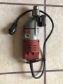
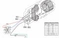
Ok, so here it goes: I want to attach a motor from a Milwaukee Mag Drill to the quick change tool post on my lathe to allow me to drill perpendicular holes in rotating stock. I thought it was going to be simple, even for me. The mechanical attachment and adjustments were, but when I started research on the motor, I discovered it was a reversible motor and I am unsure how to wire it. Since it is a reversible motor, I have to include a DPDT switch. I understand how they work, but again, I don't know how to wire the motor to 110v household current. I've searched online, including Milwaukee's Support forum. I've not been able to figure out how to complete the circuits between the household plug, the DPDT Switch and the wiring of the motor.
Please help......
…...JR


.JPG")


