24v line switching from ac - dc adapter to battery with dc - dc converter

Thread Starter

squid3083

Joined Mar 26, 2014
24
Hello everyone.

I use a DC to DC buck boost converter when I am out of Hydro power to go from a 12.5v to 24v to my CPAP machine.

Cpap Airsense 10 or 11
Specs ac to dc adapter Resmed
120v 1 amp -> 24v 2.75 max 65 watts I use less no heat plate and no heated tubing, I use on average around 30 - 35 watts.

I have a 15.6 v power bank and may buy a Lifepo4 24v 100amp battery.

The buck boost converter is a 400watt adjustable 15 amp max I use it with 12.5v to 24v with less then 3 amps

I was going to use the power bank to always be plugged in the emergency all night while it would recharge slowly from the main at night and fully recharge in day time, similar to Pilot 24 power bank.

I realized this would put too many cycles on the battery. My power bank recharges slowly by usb-c.

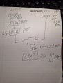
I would like to make a circuit as simple as possible while being safe to mainly take the output from the 120 v line and detect when there is outage and then switch to my power bank. When electricity would return, it would switch back to the mains.

I was suggested a DPDT relay to work on 24v or 12 with an AC control transformer on the detect line. I would be on the 120v line to my normal AC adapter by default and when the AC would be out, it would switch to the DC converter part. So in theory the 2 inputs to the relay would be the 24v from the ac adapter, and the 24v from the dc converter and output to my CPAP machine or something close to this.

It was also suggested to place series diodes on both power inputs to prevent backflow into the inactive source.

Or this relay would activate my dc to dc converter only when there is an outage so that the converter is not always on and would not use any current. Not sure how much current the buck boost converter would use if no load would be connected. In this case I would need another way to switch between the 2 24 volts line to redirect to my cpap machine.

So is this DPDT idea a simple and good idea? Is it safe for electronics? Would I need additional filter for spikes? Would I need a delay between the switches?

Thanks
 

Attachments

MisterBill2

Joined Jan 23, 2018
27,159
My first suggestion is to discover howmuch current your machine actually requires to operate. The output capability of the power supply may be more thatn your machine actually requires. Next, I suggest an investigation to see how well opthe machine can perform operating on 12 volts instead of 24 volts.
The very simplest scheme would be to simply switch to the 12 volt battery, but that might not be satisfactory.

Of course, the simplest scheme will be to buy two 12 volt 50 amp-hour batteries instead of the 100 amp-hour battery, And it might even cost less. And the scheme will avoid the losses in the 12 to 24 volt booster converter device.
A simple relay changever would be all that yo required. The batteries can be charged in parallel using a simple relay circuit as well. You might even get away with just using an isolatig diode scheme.
 

Thread Starter

squid3083

Joined Mar 26, 2014
24
My first suggestion is to discover howmuch current your machine actually requires to operate. The output capability of the power supply may be more thatn your machine actually requires. Next, I suggest an investigation to see how well opthe machine can perform operating on 12 volts instead of 24 volts.
The very simplest scheme would be to simply switch to the 12 volt battery, but that might not be satisfactory.

Of course, the simplest scheme will be to buy two 12 volt 50 amp-hour batteries instead of the 100 amp-hour battery, And it might even cost less. And the scheme will avoid the losses in the 12 to 24 volt booster converter device.
A simple relay changever would be all that yo required. The batteries can be charged in parallel using a simple relay circuit as well. You might even get away with just using an isolatig diode scheme.
I already determined that it runs on 24v if below would not turn on. That is for the air 11 and 10. they take on 24v from 0.6 to 2 maps +- closer to 1.7 1.8 when I simulate a big air leak. did this for close to 20 minutes looking at multimeter and put to retain the max value.
I would be running a fan as I need air on me which takes another 30 watts plus inverter close to 48w.

To calculate your real-world autonomy, we need to account for the "usable" energy in your
12.8v 100ah 1280wh at 90% DOD = 1152wh

Cpap 24v 2 amps = +- 15% loss for buck 56.5w x 9 hours 508.5 wh

fan 38.4 w + loss inverter 48w

fan + cpap 48 + 56.5 104.5w
9 hours 104.5w 940.5wh out of 1152wh
and if I have to use water heater at minimum as I am using might come even close.
I am too tired i asked ai to calculate for me but could not copy and paste had to retype everything
so this is why I would be buying buying the 24v

As you suggested bying to smaller in my case for the Yeagulch battery that i have selected is cheaper to buy one big instead of 2 smaller on amazon CA

I bought this morning a 4 pole relay 4pdt to send all the wires even if I needed only 3 with base from the Finder brand comercial grade. I am strugling to determine if would be better to always run from the battery and charge it at night when there is electricity or never use the battery and use the relay and have a trickle charge on my lifepo4 battery and when I loose power switch to the battery.

The AI said to bond together all the negatives together to have a one bus bar or equivalent for all negatives to be common, but check in the case of the Resmed ac - dc adapter to check that the negative was independant of the negative on the ac part, and I checked and there is no connection.
So I would not have to send the negatives in the relay, I am not sure of this. I have asked 2 AI and described the situation and both of them tell me to bind all negatives together.

Long answer but with my other post this is what occupies me for the past few days, tell me what you think. Thx
 

AnalogKid

Joined Aug 1, 2013
12,042
I was suggested a DPDT relay to work on 24v or 12 with an AC control transformer on the detect line.
Or (If I understand your request correctly), a DPDT relay with a 120 Vac coil. Connect the coil directly to the AC mains, and connect the DC sources to the contacts. This could eliminate the need for OR-ing diodes.

On ebay or alibaba there probably is a module or pc board assembly that has the relay, and terminal blocks for the wiring. No circuit, soldering.

ak
 
Last edited:

Thread Starter

squid3083

Joined Mar 26, 2014
24
Or (If I understand your request correctly), a DPDT relay with a 120 Vac coil. Connect the coil directly to the AC mains, and connect the DC sources to the contacts. This could eliminate the need for OR-ing diodes.

On ebay or alibaba there probably is a module or pc board assembly that has the relay, and terminal blocks for the wiring. No circuit, soldering.

ak
Yes a 4 pole relay with a 12 volt coil. plug in an 12 volt ac - dc adapter in the wall to have less heat in the relay and when the electricity cuts, the relay takes over.

I asked "
The AI said to bond together all the negatives together to have a one bus bar or equivalent for all negatives to be common, but check in the case of the Resmed ac - dc adapter to check that the negative was independant of the negative on the ac part, and I checked and there is no connection.
So I would not have to send the negatives in the relay, I am not sure of this. I have asked 2 AI and described the situation and both of them tell me to bind all negatives together. "

Should all negatives be bonded on a bar or bus and not send them in the relay?
Thanks

Squidly
 

sinexcel-re

Joined Jun 12, 2025
1
A DPDT relay can work for this type of setup, but there are a couple of practical things to consider.

First, switching directly between two 24V sources with a relay can cause a brief interruption when the relay changes state. Most CPAP machines tolerate a short drop, but some may reboot if the gap is long enough. Using diodes to isolate the two supplies (a simple “OR-ing” setup) can sometimes make the transition smoother and prevent backfeeding.

Another common approach is:

• AC adapter supplies the CPAP normally
• A DC source (battery + buck/boost) sits behind a diode
• When AC power disappears, the battery path automatically takes over

That way you don't actually need a relay for the power path itself, and there’s no switching delay.

If you do use a relay, adding flyback protection on the coil and some basic filtering on the output (for example a capacitor on the 24V line) can help prevent spikes when switching.

Also keep in mind that many buck/boost converters still draw a small idle current even without load, but it’s usually quite low compared with the CPAP consumption.

For reliability, the simplest design is often diode power OR-ing or a small DC UPS module rather than a relay-based switch.
 
Top