Facebook
 Google
 GitHub
 Linkedin
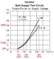
The datasheet for the TDA2050 shows a recommended schematic. The output power is 7W into 8 ohms or 13W into 4 ohms with a 24V single supply or a plus and minus 12V supply. Just build it like shown in the datasheet, you do not need to simulate it.
An ordinary modern bridged car amplifier (TDA7396) produces 9W into 8 ohms or 15W into 4 ohms with a single 12V battery or two 6V batteries. Its parts are fewer than a TDA2050. Its datasheet lists all its spec's and a recommended pcb layout.
An ordinary modern bridged car amplifier (TDA7396) produces 9W into 8 ohms or 15W into 4 ohms with a single 12V battery or two 6V batteries. Its parts are fewer than a TDA2050. Its datasheet lists all its spec's and a recommended pcb layout.