Calculations dont match multisim

Thread Starter

leejohnson222

Joined Jan 11, 2023
57
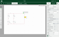
I have a circuit which i have created and i need to find current in each branch, i think i have done this, but when using a probe on the circuit i dont get the same answer, i have either made an error on calculations or not created the circuit correctly

i have 2 x 12v batteries in parallel with 2ohm anf 4 ohm resistance and the lamp at 6v 1W

current in branch 2ohms = 3A
current in branch 4ohms = 1.5A. so total of 4.5a current
where have i gone wrong?
 

Attachments

WBahn

Joined Mar 31, 2012
32,778
You are assuming that the voltage across the lamp is 6 V, regardless of what it is connected to.

All that you know is that IF the lamp has 6 V across it, then it will consume 1 W of power (at least that is what I'm assuming that the 6 V, 1 W designation means).

How it behaves at other voltages depends on the model for the lamp. The simplest model would be as a fixed resistance, but that isn't very realistic, particularly if it is supposed to be modeling an incandescent lamp, in which the resistance is usually a strong function of temperature, with the resistance going up as the temperature goes up.

You have the information to back out the operating point of the lamp for the circuit in the simulation.

V1 is an unknown voltage, but you know the current leaving that node and going into the lamp.

So can you set up a KCL equation that will let you solve for V1?

What does this indicate that the lamp resistance is at this operating point?

What would the lamp resistance need to be to dissipate 1 W with 6 V across it?

How do these two resistances compare?
 

Thread Starter

leejohnson222

Joined Jan 11, 2023
57
so this is a question i am trying to solve and then confirm with the simulation,
so far i have..
Lamp load
IL = PL/VL 1/6 = 0.1667a

Thevenin resistance Rth = Rs1 || Rs 2 = 2 x 4 / 2 +4 = 1.333ohms

Vth = 12v

look at node voltage with load circuit and use kcl
V = 6v

Is1 = 12 -6 / 2 = 3a

Is2 = 12-6/4 = 1.5a

supply can be 4.5a but lamp load is 0.1667a

i think the resistance of the light source is 35.99 ohms ?

i am not sure how i draw this to confirm my working out, i thought i would recreate the circuit and the amp meter would read 4.5a going into the lamp,
 

WBahn

Joined Mar 31, 2012
32,778
so this is a question i am trying to solve and then confirm with the simulation,
so far i have..

Lamp load
IL = PL/VL 1/6 = 0.1667a
You need to track your units properly. This should be

IL = PL/VL 1 W / 6 V = 0.1667 A

This is the current that the lamp will have flowing through WHEN it happens to have 6 V across it. Put something other than 6 V across it, and it will have a different current. Increase the voltage, and both the current through it and the power dissipated in it will go up; decrease the voltage across it, and both the current through it and the power dissipated in it will go down.

Thevenin resistance Rth = Rs1 || Rs 2 = 2 x 4 / 2 +4 = 1.333ohms
Not only do you need to track units, but you need to be careful about order of operations. If you evaluate the expression 2 x 4 / 2 +4 you get 8.

This should be

Thevenin resistance Rth = Rs1 || Rs 2 = 2 Ω x 4 Ω / (2 Ω + 4 Ω) = 1.333 Ω

Vth = 12v
Use proper units. Amperes is 'A', not 'a'. Volts is 'V', not 'v'.

Okay, so now you have Vth in series with Rth and some unknown resistance for the lamp.

look at node voltage with load circuit and use kcl
V = 6v
Once again, you are assuming that the voltage across the lamp is somehow magically fixed at 6 V.

What if the lamp is unplugged and sitting in a box on a shelf? Is the voltage across it going to be 6 V?

What if I connect the lamp across a 1000 V battery? Is the voltage across it going to be 6 V?

The actual voltage across the lamp is determined by the interaction of the lamp and the circuit it is connected to.

Is1 = 12 -6 / 2 = 3a

Is2 = 12-6/4 = 1.5a
Same issues with units and order of operations.

supply can be 4.5a but lamp load is 0.1667a
Because of the faulty assumption you keep making that the lamp somehow always has 6 V across it no matter what it is connected to.

i think the resistance of the light source is 35.99 ohms ?
That's based on it's resistance at one particular operating point, namely when it has 6 V across it and is therefore dissipating 1 W. For a real incandescent lamp, the resistance at different voltages will be a lot different. But your Multisim model for a lamp may be so simplistic that it treats the lamp resistance as a constant.

So make that assumption and see what you get. Put 36 Ω as the lamp resistance, in series with Vth and Rth, and see what you get for the current. Does it match the 166.7 mA of the simulation? If so, then you know that Multisim is, indeed, using a constant resistance for the lamp. If not, then you know that it is using some other model.

You can go the other way, too. You know the current that the sim says is flowing in Rth (since it is in series with the load), so use that, combined with Vth, to find the actual voltage across the lamp. Then use that, along with the current flowing through the lamp, to find the lamp's resistance at that voltage.

i am not sure how i draw this to confirm my working out, i thought i would recreate the circuit and the amp meter would read 4.5a going into the lamp,
Hopefully the above gives you some ideas. But you first need to get over this notion that the lamp somehow always has 6 V across it. Just stop!
 

Thread Starter

leejohnson222

Joined Jan 11, 2023
57
right so then, if i have Rth = 1.333ohms Vth = 12V RL = 36ohms

I dont think you can add a resistance to the lamp in the sim, so i will use a resistor
Current shows 163.64mA so its not exactly 166.7mA

You lost me on the other way to look at it, but its been a long day, may need a fresh look later in the week
 

Attachments

WBahn

Joined Mar 31, 2012
32,778
right so then, if i have Rth = 1.333ohms Vth = 12V RL = 36ohms

I dont think you can add a resistance to the lamp in the sim, so i will use a resistor
Current shows 163.64mA so its not exactly 166.7mA

You lost me on the other way to look at it, but its been a long day, may need a fresh look later in the week
The lamp is a component in your simulation library. It has some kind of voltage-vs-current characteristic as part of its model. That model may well be something as simple as it being treated like a constant 36 Ω resistor. You don't need to add another resistor to the circuit -- the lamp component already has it built in.

So your circuit is now a 12 V source across the series combination of a 1.33333 Ω resistor, a 36 Ω resistor, and a 36 Ω resistor (the lamp), making a total of 73.33333 Ω. The current you would then expect to see is

I = 12 V / 73.33333 Ω = 163.6364 mA (which matches the simulation to the number of digits displayed).
 

WBahn

Joined Mar 31, 2012
32,778
so i have done it wrong then as it doesnt confirm my figures, or my figures are wrong here
How are those figures wrong?

Your original simulation showed 321.43 mA going through the lamp.

Your new simulation, in which the circuit to the left of the lamp has been replaced with its Thevenin equivalent, shows 321.43 mA going through the lamp.

How do those not match?

You appear to still be trying to insist on the voltage across the lamp being 6 V. It isn't. It's 11.571 V.

Take your original circuit and throw the lamp away. In it's place, put a 36 Ω resistor. Not analyze the circuit and determine what the voltage across that 36 Ω resistor is and what the current flowing through it is. You will get a voltage of 11.571 V and a current of 321.43 mA.
 

Thread Starter

leejohnson222

Joined Jan 11, 2023
57
yes after checking all my working out i can see the current and the simulation showing the same results, i was getting it round my neck for some reason. I appreciate the push to get this making more sense
 

MisterBill2

Joined Jan 23, 2018
27,371
How are those figures wrong?

Your original simulation showed 321.43 mA going through the lamp.

Your new simulation, in which the circuit to the left of the lamp has been replaced with its Thevenin equivalent, shows 321.43 mA going through the lamp.

How do those not match?

You appear to still be trying to insist on the voltage across the lamp being 6 V. It isn't. It's 11.571 V.

Take your original circuit and throw the lamp away. In it's place, put a 36 Ω resistor. Not analyze the circuit and determine what the voltage across that 36 Ω resistor is and what the current flowing through it is. You will get a voltage of 11.571 V and a current of 321.43 mA.
Certainly this is a trick circuit because if you do not know the resistance of the lamp, or the current, or the actual voltage across it, there is no way to calculate those values. ALSO, as stated a few times, the lamp resistance varies with the temperature, which varies with the current. Where did you get this circuit, anyway? Replacing the lamp with a fixed resistor of any value will allow the solution to be found, As has already been stated correctly.
 

WBahn

Joined Mar 31, 2012
32,778
Certainly this is a trick circuit because if you do not know the resistance of the lamp, or the current, or the actual voltage across it, there is no way to calculate those values. ALSO, as stated a few times, the lamp resistance varies with the temperature, which varies with the current. Where did you get this circuit, anyway? Replacing the lamp with a fixed resistor of any value will allow the solution to be found, As has already been stated correctly.
Agreed -- and, as noted, those issues were mentioned right away. The data provided in the very first post is sufficient to have very high confidence that the lamp model for this simulator is a fixed resistor. That first post gives two data points. The first one is that the lamp dissipated 1 W when it has 6 V across it. That means that the effective resistance of that lamp with 6 V across it is 36 Ω. But we also have all the information needed to find the voltage across the lamp when it has the indicated current of 321.43 mA flowing through it by solving for the voltage on the top node that is required to get that total current flowing from the two 12 V sources. That turns out to be 11.571 V. With that, we then know that the effective resistance of the lamp with 11.571 V across it is, once again, 36 Ω. While not impossible, it is unlikely in the extreme that some nonlinear lamp model is being used that just happens to have an effective resistance of 36 Ω at those two operating points. The sim result provided later pretty much nailed that coffin shut since it shows 36 Ω for the lamp at yet another operating point.
 
Top