 Facebook
 Google
 GitHub
 Linkedin
Hello everyone,
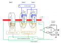
Im looking for some guidance on how to design my own closed loop fluxgate, i found this link: Zero Flux White Paper so im kinda going with this.
I have picked out my Cores "T60006-L2160-V074" from Vacuumschmelze as i have already worked out my basic parts.
My primary conductor is a copper rectangle arranged in 2x2 form where 1 conductor has the dimensions 50cm length, 25cm height and 4cm width. Soldered together at the ends.
The goal is to design it for ~1000A, i have already tested the the simple circuit - Transformer - Primary conductor. It works perfectly fine up to ~1800A.
My question now is how do i go about designing the electronics for it.
Any help would be greatly appreciated!
- Philip
Attachments
-
 165.6 KB Views: 20


