Diode question

MrAl

Joined Jun 17, 2014
13,704
I must admit that I do not use any model.
And in my contributions I did not speak about models but on transistor physics.
I am aware that models do not necessarily always reflect physical laws (in the sense of cause and effect).
Some models are good for calculation purposes only.
In any case, we should really try to distinguish between models and physical explanations - otherwise misunderstandings and misinterpretations cannot be avoided (as we can see here in this thread).

As I can read - you would "really like to hear what he has to say on this subject."
OK - here is my answer:
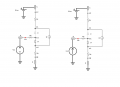
You are wrong - all detailed Spice models do NOT use a controlled current source.
If you would look into the model descriptions you will notice that all Spice models, of course, are based on the classical exponenetial relationship Ic=f(Vbe).
This is absolutely necessary because these models must work for small-signal as well as large signal operation.
(Do you know about a current-controlled model for large signal operation?)
I hope I have answered all of your questions.
Hi and thanks for the reply,

If you do not use any model then how do you calculate the collector current for example?

The Gummel Poon seems to use a current controlled current source, NOT a voltage controlled current source. There is of course more to it though. In the attachment It is dependent on If mostly until we get near saturation.

I am drawing attention to the fact that even a transistor is a passive device, in that it cannot really generate any power on its own without some sort of stimulus. To generate a current in the collector requires energy.

Consider the simple resistor. We of course have V=I*R, but don't we also have I=V/R. Is the resistor current controlled or voltage controlled. How about a simple diode. We can calculate the current from the voltage, or the voltage from the current, so is the diode current controlled or voltage controlled.

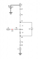
Now consider the drawing in the attachment paying attention to "iB" with direction indicated by the red arrow.
Can you show how you can get iC greater than zero with iB being zero? In other words, how can you get iC to be maybe 10ma with iB=0.
The main diode (darker shade) gets a voltage across it AND a current through it, and that means there has to be current into the base.

It appears that the way we calculate this stuff depends on what we are measuring. If we measure voltage first, it appears that we are looking for the current response, and if we are measuring current first, then we are looking for the voltage response.

The 'physics' of the transistor is still just a model, so I don't think that changes much. In these kinds of devices current and voltage are considered to appear simultaneously. If we apply a voltage we get a current, and if we apply a current we get a voltage. This is why I mention the application of the transistor as a requirement.
 

Attachments

MrAl

Joined Jun 17, 2014
13,704
Take a closer look at that Gummel-Poon model.

The current source is dominated by (if - it) which are both functions of voltage, not current.
Hi,

Yes that's a good point, but it is a current controlled current source nonetheless.

That shouldn't be the main point though I don't think. In short we are looking at i(vf) and i(vr), but to make it even simpler we can look at just i(vf) for now, or just i(v) which is the current as a function of voltage.

When we have a function like y=f1(x) we also have an inverse function x=f2(y). Either f1 or f2 may not be easy to calculate, but it's always a possibility, given the required constraints. So why should we insist that f1 or f2 is the correct choice exclusively.

In the attachment, I do not see any way that we can get any iC without at least some iB, and it even looks to be monotonic or nearly so. I also do not see any way to get any iC without some vBE. So why choose one over the other.
(The upper diode is grayed out to make the model even simpler because we don't have to think about saturation just yet).

Also consider a silicon solar cell. I think we can agree that it is light (radiation) dependent, and it's hard to say that it is also dependent on applied voltage. Is it possible that it emits some radiation if a voltage is applied? I guess so, but that's so off the charts that we would only have to consider it in a very particular application. It's still not impossible though.
Comparing this kind of control to the transistor control illustrates the wide differences in something that is highly controlled by one mechanism and only subtly controlled by another mechanism, and something that has a shared control mechanism.
 

Attachments

Last edited:

MisterBill2

Joined Jan 23, 2018
27,523
The unmentioned thing that these recent discussions point out is what changes with temperature lead to thermal runaway in some devices, such as bipolar transistors. Compensating for one sort of weakness is different from understanding what causes it. So this has indeed been a thread that will benefit those just starting out.
 

MrAl

Joined Jun 17, 2014
13,704
The unmentioned thing that these recent discussions point out is what changes with temperature lead to thermal runaway in some devices, such as bipolar transistors. Compensating for one sort of weakness is different from understanding what causes it. So this has indeed been a thread that will benefit those just starting out.
To me bringing in temperature at this point just complicated the discussion. Temperature is of course a consideration but we don't always have to think about that. If we did we'd have to consider the effect of "Is" too which varies with temperature. That can change things a lot but does not seem to support either current or voltage dependency as the primary control mechanism.
 

Bordodynov

Joined May 20, 2015
3,431
See which is better: setting the mode with a voltage source or a resistor (current source). I also deduced the overheating of the transistors.

1735102463838.png
 

MrAl

Joined Jun 17, 2014
13,704
The bad news is that the real world is complicated. Sometimes we can get away with ignoring that, other times no, we can't ignore it.
Hi,

Yes, and here we are really concerned about voltage and current which would be considered to run along two orthogonal directions like the x and y axes. To bring in temperature brings in a 3rd dimension which does not help to resolve issues with the first two dimensions.
We almost always like to think in terms of individual dimensions because that's how we can comprehend the influences of the individual dimensions when we need to. In fact, when we have equations that do not fit into that kind of structure, it helps enormously to rotate them so that we can analyze results independently for each single dimension alone. If we find we can't do that, then we can conclude that at least one of the dimensions is redundant. For the voltage and current or voltage vs current discussions, we don't really care what the temperature is doing simply because we are trying to decide the importance of two other quantities. Of course we may need temperature for other discussions.

I'll post an illustration of how we might go about deciding this in the next post because it's related to another reply also.
 

MrAl

Joined Jun 17, 2014
13,704
See which is better: setting the mode with a voltage source or a resistor (current source). I also deduced the overheating of the transistors.

View attachment 338882
Here's the way I did it. The question was about current and/or voltage, so that's what I tested. Using one voltage source and one current source, and the two were correlated such that when the voltage source went up by 1v the current source went up by 3ma, and the correlation was perfect (so 2v and 6ma, 3v and 9ma, etc.) so they were essentially synchronized. (See illustrations).


I found that the main difference was that when using voltage control the collector current does not start right away because as the BE voltage rises it starts from zero and between 0 and about 0.6 volts we do not see any collector current. When using current control, the collector current follows the base current from 0 and up, and is almost linear. For voltage control it is quite linear also but just does not work until the voltage gets up to that 0.6v level or so.
So both ways work to control the collector current, and the current control is very close to linear, and with voltage control it is also linear except in that no response zone. The voltage control looked more linear within the active range, and the transistor used was the 2N2222A, although models will vary from simulator to simulator and between the spice models themselves.

It's also interesting (not shown yet) is that if we want to solve for the input current with a voltage source driving the base emitter, it is not too hard to do if we solve for the voltage not the current directly. It's also interesting that when we use current control we don't have to solve for any voltage because we always know the diode current (after all it's a current source powering a diode). That must be where the expression iC=iB*Beta comes from.

Note Re is zero for my tests, and so is Rb. In the simplified model since It=If we know what 'It' is right away when we use current control. This also hints at the requirement for knowing the application we are dealing with.
Rc was different for the two circuits such that we never went into saturation with either.
The curves looked almost like straight lines, except the voltage control curve did not show any collector current until after we go up to that 0.6 volt threshold.

Note I did not bring in charge control for comparison for the same reason I did not bring in temperature control, because it just does not matter when trying to decide between current and/or voltage control. That would also bring in some of the capacitances usually associated with the models which is really unnecessary (can't have any charge storage without capacitance) because we only need to look at DC cases.
 

Attachments

Last edited:
Top