Diode oscillates at low currents?

Thread Starter

Maverik

Joined Jul 24, 2012
5
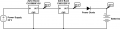
So we're using a diode that is something like this except a little older so I can't find a datasheet.

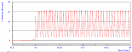
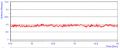
It's rated at really high currents and it works really well when we put large amounts of current through it, but we're noticing that when we put lower currents (<15amps) we're getting a ~20 Hz oscillation on it. I'm attaching pictures for reference.

Has anyone ever encountered this? Do you know what might cause this?
 

Attachments

alfacliff

Joined Dec 13, 2013
2,458
it might be a slight problem with the diode. if the doping were wrong, it might be acting like a tunnel or Esaki (sp?) diode. those exhibit negative resistance and will oscilate. I have never seen one do this though.
 

Thread Starter

Maverik

Joined Jul 24, 2012
5
Lol, sorry I totally forgot about the circuit around it.

We're boosting up a voltage and the bucking it back down. The reason I thought it was the diode was because we bypassed it and we got the smooth output.

Today I hooked up the diode across a power supply and limited to 10 amps and under and got no oscillations, so I'm thinking it has something to do with the combination of the output filter and the power diode to give us a weird control loop.

Anyone experience anything like this before?
 

Attachments

THE_RB

Joined Feb 11, 2008
5,438
Put a large cap (with LOW ESR) directly on the output of the Buck module.

Your circuit as it stands allows the diode characteristics to interfere with the closed loop voltage regulation of the buck module, causing it to oscillate.
 

tindel

Joined Sep 16, 2012
939
Constructive critisism, please don't take it the wrong way:

Why are you boosting, bucking, and then using a crappy (2V!) diode to produce 43V? You'll end up with horrible efficiency and poor regulation... Why not just boost your 24V supply to 43V and be done with it?

If you're using a diode to 'diode-or' 2 supplies then I get what you're doing, but even so, there are much better power diodes that provide less voltage drop than 2V at heavy loads, and it would be better to just have a single converter stage still.
 
Last edited:

Thread Starter

Maverik

Joined Jul 24, 2012
5
I'm using a boost and then buck because the buck offers current limiting. The voltage drop is estimated, I'm not concerned with efficiency as much as I am about proof of concept and this is injected into a larger system.
 

SgtWookie

Joined Jul 17, 2007
22,230
Well, those supplies are a couple of grand each; why not consult with the manufacturer and get ONE boost-type supply that will meet your requirements? Also, you could replace that diode with (a) MOSFET(s) used as ideal diodes to eliminate the majority of that 2v drop across the diode.
 

alfacliff

Joined Dec 13, 2013
2,458
I have seen supplies like this before, but they were used at line levels to boost the line voltage to around 350 volts then had multiple output modules running off them for whatever output voltages you need. sola makes some, and astec makes them also.
 

Thread Starter

Maverik

Joined Jul 24, 2012
5
Well, those supplies are a couple of grand each; why not consult with the manufacturer and get ONE boost-type supply that will meet your requirements? Also, you could replace that diode with (a) MOSFET(s) used as ideal diodes to eliminate the majority of that 2v drop across the diode.
I'd love to have the manufacturer build a specific converter for us, but he was not interested. We're not ordering a lot (University Research), so he isn't really inclined to spend much time with us. I will look into replacing the diode with MOSFETs, it's just going to be slightly annoying to add additional driver circuits and the sort as we run around 100-300 amps through here.

Thanks everyone for the input, it has been very helpful.
 
Top