 Facebook
 Google
 GitHub
 Linkedin
Hello,
I would never thought I could not understand a circuit made out of diode but here I am.
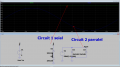
1-the first circuit is two diode in series, when i measured the voltage between the them I found it half the voltage of the source which is not logic for me!!! as there is no current flowing through the diode, so how can it be a voltage divider!!!
2-diode in parallel and opposite to each other, for my understand it should show an output of +/-0.7V, but I got a full wave of source signal!!!
can anyone clarify for me these two circuits?
I would never thought I could not understand a circuit made out of diode but here I am.
1-the first circuit is two diode in series, when i measured the voltage between the them I found it half the voltage of the source which is not logic for me!!! as there is no current flowing through the diode, so how can it be a voltage divider!!!
2-diode in parallel and opposite to each other, for my understand it should show an output of +/-0.7V, but I got a full wave of source signal!!!
can anyone clarify for me these two circuits?
Attachments
-
 66.2 KB Views: 75
Last edited:


