My answer is no. There is no generalized solution for solving such problems. You have to examine each situation and apply a method that you think suits.
The two analyses show that 6.23 V will cause D2 to be reverse biased.
Hence D1 is forward biased and D2 is reverse biased.
I never suggested superposition.
The best bet here is to first try to grasp what is going on and what should be taken into account. Try to get some understanding about what is going on in this circuit.
First, we have the lesser source on the right, and if the 9v was not there it would mean the top of the middle diode would assume the voltage according to the 4v source, the two diodes, and the 2k resistor. Once you know what the voltage is there, you can then look at what happens when you replace the 9v source and the 7k resistor it connects to. Does it look like it will change the voltage at the top of the middle diode?
There are a few general ways of solving this for any circuit. The first is the one described above and also in post #4 which is probably the simplest way.
The most general way is to consider that the diodes are switching elements, each with 2 states, 'on', or 'off'. We can draw a little truth table were '0' means off and '1' means on, and the first column can be for the diode on the right and the second column for the diode in the middle:
0 0
0 1
1 0
1 1
Each line represents one system state, and you can try all four of those combinations, checking each time if the voltages and currents are correct for that state. If they are correct, then you have a solution. There may be times when you get two or more solutions but that would be rare except in a more balanced circuit.
If you had three diodes you'd have 8 system states:
000
001
010
011
100
101
110
111
and with four diodes 16 states, so you can see that with each additional diode you get double the previous number of states.
Another way which is probably harder to do by hand, is to raise the voltage of each source little by little and after each change check to see which diodes are conducting, if any. What can help in this scenario is to place a one or more capacitors with one lead connected to well chosen nodes and the other lead connected to ground, then do a time domain analysis. You can then solve for the time(s) that the diodes turn on, and you don't have to step the two sources this way.
This also leads to the more general view that involves as partial differential equation where we solve for both a voltage 'v' and a time 't'. The time 't1' could be the time when one of the diodes turns on, and time 't2' when the other diode turns on. This is probably the most general way to look at these networks especially when they already have capacitors in them already.
This turns out to be incredibly interesting too and works in AC and DC circuits in the time domain too.
so trying each case as truth table is only way to solve this kind of problem, is there any shorter way? one man above told me to remove each source, I wonder how he can invent that method?
so trying each case as truth table is only way to solve this kind of problem, is there any shorter way? one man above told me to remove each source, I wonder how he can invent that method?
Yes, you need to take an intuitive look at the circuit first as I mentioned and try to visualize what might be happening. I reinstated that other method also, because it is faster when the circuit is not too complicated. You start with the lowest voltage source with the higher one disconnected, as that post had outlined. You then calculate the voltage at the node that the two sources 'share'. They share the central node above the center diode because they both are providing current to that node. You calculate the voltage at that node with just the lower voltage source, then apply the higher voltage source and think about how that changes things.
If you have trouble doing that, then connect a capacitor from that shared node to ground, then do a time domain analysis and calculate the time when each diode turns on or off. As that shared node voltage rises, the state of the two diodes will change, perhaps more than once. You can use a circuit simulator to see how this works, and look at the voltage across each diode and the current through each diode.
There is yet another method but you have to be familiar with curve fitting. This would probably take too much time to learn though.
There's also a matrix method too but I'd have to look that up to remember it myself I haven't used that in a very long time now.
Maybe it would help if we went over a different example, then you could come back to this one and see if you can solve it easily.
Can you give me a book on this problem or another relevant example with multiple sources and diodes, harder to try. I think with that one we cannot use truth table.
Can you give me a book on this problem or another relevant example with multiple sources and diodes, harder to try. I think with that one we cannot use truth table.
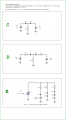
Here are two more problems to start with. They should not be too hard to figure out. You just have to find out what voltages E1 takes on when each set of diodes just starts to conduct.
We assume that when the voltage across a diode is less than 0.7v the diode does not conduct, and when the voltage reaches 0.7v across the diode it is about to start to conduct. So what you have to calculate is when the voltage across each diode goes from less than 0.7 volts to 0.7 volts.
Also, once the diode starts to conduct, its voltage remains at 0.7 volts exactly, and then the associated resistor will start to have current though it as the voltage is raised a tiny bit more.
If you have any questions about either circuit A or B just let me know.
Next, I'll post some two source problems for you to try.
Another thing you can try is to replace each diode with a voltage source equal to its forward voltage and see if the circuit makes sense. If not, one or more of the diodes must be open circuit (not conducting).
Yes, you need to take an intuitive look at the circuit first as I mentioned and try to visualize what might be happening. I reinstated that other method also, because it is faster when the circuit is not too complicated. You start with the lowest voltage source with the higher one disconnected, as that post had outlined. You then calculate the voltage at the node that the two sources 'share'. They share the central node above the center diode because they both are providing current to that node. You calculate the voltage at that node with just the lower voltage source, then apply the higher voltage source and think about how that changes things.
If you have trouble doing that, then connect a capacitor from that shared node to ground, then do a time domain analysis and calculate the time when each diode turns on or off. As that shared node voltage rises, the state of the two diodes will change, perhaps more than once. You can use a circuit simulator to see how this works, and look at the voltage across each diode and the current through each diode.
There is yet another method but you have to be familiar with curve fitting. This would probably take too much time to learn though.
There's also a matrix method too but I'd have to look that up to remember it myself I haven't used that in a very long time now.
Maybe it would help if we went over a different example, then you could come back to this one and see if you can solve it easily.
I ve got this shorter way, wonder if it is correct? I replaced each diode with a voltage source 0.7v , then use mesh method find I1, I2, because I2 in reverse direction with horizontal diode then actually it is reversed bias and no I2 current then we have I1 = 8.3/3 =2.7A then calculate voltage across vertical diode, this way is much simpler. View attachment 1742057025013.jpeg
I ve got this shorter way, wonder if it is correct? I replaced each diode with a voltage source 0.7v , then use mesh method find I1, I2, because I2 in reverse direction with horizontal diode then actually it is reversed bias and no I2 current then we have I1 = 8.3/3 =2.7A then calculate voltage across vertical diode, this way is much simpler. View attachment 344609
I ve got this shorter way, wonder if it is correct? I replaced each diode with a voltage source 0.7v , then use mesh method find I1, I2, because I2 in reverse direction with horizontal diode then actually it is reversed bias and no I2 current then we have I1 = 8.3/3 =2.7A then calculate voltage across vertical diode, this way is much simpler. View attachment 344609
This approach is just starting with the assumption that all of the diodes are conducting and then identifying whether or not the resulting solution is consistent with that assumption. If any of the diodes have reverse current flowing in them, then you know that your assumption was incorrect for at least one of those diodes (and that, most probably, one of the diodes that has reverse current is actually reverse biased). But, in general, this approach is not sufficient to identify exactly which diodes are and are not conducting, only that your overall assumption that all diodes are conducting was incorrect. So now you have to revise your assumptions and redo the analysis. In a simple case like this two-loop circuit, just assuming that the mesh current through the reverse-biased diode is zero should work, but in a slightly more complicated circuit, that won't necessarily be the case.
The approach that I have generally found to work the best, unless something jumps out for that particular circuit (which is often the case) is to virtually ramp up the supply voltages and determine the transition points. Then you have a map of which diodes are on or off depending on the input voltage.
The diode has either a forward or a reverse bias orientation. So, place a label on the diode to indicate the bias orientation.
The first example the diode has a forward bias. The second example the diode has a reverse bias. (orientation)
In the last example D3, a major voltage drop to 699mV occurs when the diode is flipped horizontally. Forward bias
When the diode is flipped back then it has a reverse bias orientation. Changing the resistor values it still agrees with Mr Chips.
I ve got this shorter way, wonder if it is correct? I replaced each diode with a voltage source 0.7v , then use mesh method find I1, I2, because I2 in reverse direction with horizontal diode then actually it is reversed bias and no I2 current then we have I1 = 8.3/3 =2.7A then calculate voltage across vertical diode, this way is much simpler. View attachment 344609
With time related sources you are effectively solving for both voltages and time values.
For many circuits we just solve for voltages or currents, but for some circuits we also have to solve for time values like 1.34 seconds. Diodes are switches that switch depending on the voltages across them.
A simple example is a sine source 100*sin(wt) and a diode and resistor in series being driven by that source. We have to solve for the time when the diode voltage reaches 0.7 volts. This is a very simple example of course, because the solution is just 100*sin(wt)=+0.7 volts, and we just solve for time 't'. When we add capacitors however, it means we have to solve for the voltage as well as the time 't'. It's quite interesting and leads to some intuition about these circuits.
The most interesting application for this is a full wave rectifier circuit with capacitor filtering and resistive load. We have to solve for the diode turn on times as well as the voltages. There is a closed form solution that comes out of this, but as soon as we increase the complexity of the circuit a little (like by adding capacitor ESR) the analysis gets more involved as solving for the voltages and times becomes more complicated.
Oh ok, ha ha, yes I tend to like to be very explicit so there is less to misunderstand. You have to be patient in some cases and read everything and that way you don't miss anything. You could miss something important.
Here's another interesting circuit that questions when the diode gets forward biased and when it doesn't. I've included a simulation snapshot so you can see what is going on. We just have to solve for the times when the diode turns on and when it turns off. The diode waveshape is a little curved in this example because it uses a spice model, but in a hand calculation with a diode with drop 0.7v it may come out completely flat, and the rise and fall times may be much much faster.
Units are Ohms, Farads, and Volts, and time in seconds.
The red wave is the input sine with 100v peak at a frequency of just 1Hz, and the blue wave the output at node Vo1. The times the diode switches would be the times when its waveform goes through zero.
I have a more elaborate example with a full wave rectifier circuit I'll post at a later date. Not sure if you want to get that into it or not.
 Facebook
 Google
 GitHub
 Linkedin


") or did you mean that mesh analysis has something integral to do with it?
or did you mean that mesh analysis has something integral to do with it?


