 Facebook
 Google
 GitHub
 Linkedin
Hi all
I am progressing well in the book thanks to all!
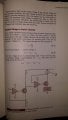
I am now doing Voltage Control Current Source,
a) Marked on both images with circles 1 and 2, Are the resistors function are like two current sources(with a PNP transistor)? Am I correct?
b)In figure 20-22 says that when the load resistance increase the transistor become saturated. My difficulty, is the transistor became saturated by the load, independent to the base current supplied by the opamp? Am I correct?
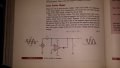
c)In grounded Voltage-to-Current Converter fig 20-23 I have a question regarding the derivation That the author writes that:
" the current through the first transistor is i=Vin/R,
This current produces a collector voltage of Vc=Vcc-Vin"
My thoughts are: if the voltage that is across the lower resistor(on the left Fig20-23) is Vin(inverting input is within micro volts of the noninverting input) supplied by the inverting input of the opamp therefore the current that passes through the lower resistor (on the left of Fig20-23) i=Vin/R, since the same current passes(Ie=Ic) through the upper resistor (on the left Fig20-23) the voltage across the upper resistor is Vin(because it has the same resistance value as the lower resistor and the same current Ie=Ic) ,therefore the voltage of the collector with respect to ground is Vc=Vcc-Vin, Am I correct?
sincere thanks
Sm
I am progressing well in the book thanks to all!
I am now doing Voltage Control Current Source,
a) Marked on both images with circles 1 and 2, Are the resistors function are like two current sources(with a PNP transistor)? Am I correct?
b)In figure 20-22 says that when the load resistance increase the transistor become saturated. My difficulty, is the transistor became saturated by the load, independent to the base current supplied by the opamp? Am I correct?
c)In grounded Voltage-to-Current Converter fig 20-23 I have a question regarding the derivation That the author writes that:
" the current through the first transistor is i=Vin/R,
This current produces a collector voltage of Vc=Vcc-Vin"
My thoughts are: if the voltage that is across the lower resistor(on the left Fig20-23) is Vin(inverting input is within micro volts of the noninverting input) supplied by the inverting input of the opamp therefore the current that passes through the lower resistor (on the left of Fig20-23) i=Vin/R, since the same current passes(Ie=Ic) through the upper resistor (on the left Fig20-23) the voltage across the upper resistor is Vin(because it has the same resistance value as the lower resistor and the same current Ie=Ic) ,therefore the voltage of the collector with respect to ground is Vc=Vcc-Vin, Am I correct?
sincere thanks
Sm
Attachments
-
 490.8 KB Views: 17
 -
 347.4 KB Views: 15

")


