 Facebook
 Google
 GitHub
 Linkedin
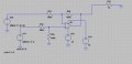
I UNDERSTAND THAT THIS IS JUST AN INVERTING AMP. I AM JUST TRYING TO GET THE DIFFERENTIAL PART WORKING BEFORE I PUT THE OTHER SOURCE ON THE POSITIVE TERMINAL OF THE AMP.
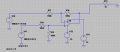
I am attempting to create a differential amplifier using an LM324, and four 100k resistors. The schematic is below.

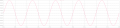
I am taking the output at Node3, and getting the correct SIMULATION results.

The problem is coming when I put it all together and physically simulate it. I have the hardware set up correctly, but I am not getting what I want out of the circuit.
Node 1 is performing correctly, but I am getting nothing out of the output. I am using an LM324n. The simulated circuit is an ideal opamp. Could this be the problem? I have the hardware hooked up correctly (as inspected by two other engineers, as well). I cannot figure out why it will not give me the output I desire. Is there something obvious that I am doing incorrectly?
The one part of the circuit I do not understand is that when, on my Agilent 33250A Function Generator, I switch from "High Z" output impedance to 50ohm impedance, I am getting effectively double. Why is this?
I am attempting to create a differential amplifier using an LM324, and four 100k resistors. The schematic is below.
I am taking the output at Node3, and getting the correct SIMULATION results.
The problem is coming when I put it all together and physically simulate it. I have the hardware set up correctly, but I am not getting what I want out of the circuit.
Node 1 is performing correctly, but I am getting nothing out of the output. I am using an LM324n. The simulated circuit is an ideal opamp. Could this be the problem? I have the hardware hooked up correctly (as inspected by two other engineers, as well). I cannot figure out why it will not give me the output I desire. Is there something obvious that I am doing incorrectly?
The one part of the circuit I do not understand is that when, on my Agilent 33250A Function Generator, I switch from "High Z" output impedance to 50ohm impedance, I am getting effectively double. Why is this?
Attachments
-
 45.5 KB Views: 15
 -
 7.6 KB Views: 15
 -
 17.6 KB Views: 16
 -
 8 KB Views: 15


