Different Amperage Depending on Where I Measure

LesJones

Joined Jan 8, 2017
4,509
You started by describing the problem as related to just strings of LEDs with no mention of the controller.
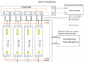
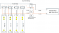
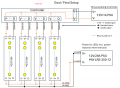
Whot you have in post #20 is more complicated so for us to fully understand it you need to provide us with the information provided with the controller and with the LED arrays.
On the connector at the bottom left of the controller there seems to be a middle terminal marked V+ in light grey. Does this terminal exist ? I suspect that the wires between the controller and the LED arrays are only expected to carry data. (NOT PROVIDING CURRENT TO POWER THE LEDs.)
It is not possible for the current reading to be different in the negative and positive wires from the power supply. The resistance of the current meter would be seen by the controller/LEDs as exactly the same value when in either wire.

Les.
 
Last edited:

WBahn

Joined Mar 31, 2012
32,929
It is not possible for the current reading to be different in the negative and positive wires from the power supply. The resistance of the current meter would be seen by the controller/LEDs as exactly the same value when in either wire.

Les.
But the effect of that resistance can be very different. If the controller is a current controller, it has to measure the current somehow. If it does that using a voltage referred to V-, then the presence of the meter resistance in that path changes the current sensing circuit, most likely resulting in the controller thinking that the current in the LEDs is more than it really is.
 

MisterBill2

Joined Jan 23, 2018
27,672
What has become obvious to me is that either the circuit shown is not actually correct, or that conditions change between making measurements in the two feed lines from the one supply.
Certainly the guess that the negative sides of the two supplies are not totally isolated is a reasonable guess, and the fact that disconnecting the one lead from the one supply immediately increased the current reading to the same value proves that the second supply was providing current.

So the correct explanation is that the circuit shown was not correct at all, because it did not show the connection between the two power supplies. Just because it was not understood or known does not mean it was not having an effect.

Providing adequate current capability in the wiring would have removed the need for adding a second power supply. Inadequate wire connections are often the source of rather strange problems.
 

LesJones

Joined Jan 8, 2017
4,509
BobTPH, I should have specified when I said " It is not possible for the current reading to be different in the negative and positive wires from the power supply. " that I was refering to the drawing in post #20

Les.
 

Thread Starter

mulu

Joined Aug 4, 2024
16
My apologies.
1) I should never have mentioned the second power supply. This is not what I did for this post. It's just what my final goal is.
2) I realized that my drawing was incorrect. The position where I indicated I am reading the current was incorrect.

CurrentSetup.png -> This is what I currently have, i.e. about what I wrote in this post.
GoalFinalSetup.png -> This is the end goal with two power supply.

Orange is where the "return path" to V- is. Now it actually becomes clear, that 6A is going back over that 14AWG cable and the other 7A are going back over the 4 24AWG cables. I am a bit surprised about this because 4x 24AWG should have a higher resistance than 1x 14AWG. So I am not sure why so much current is going back through the controller.

The controller would be able to provide everything directly. However, the controller is somewhat far away from the LEDs. Hence, there is too much power loss for V-/V+. Therefore, I leave the controller where it is, don't use V+ and instead bring a second power supply closer to the LEDs. That's actually what people do anyways for power injection.

My concern now is, that there is a return patch to V- via the controller, i.e. that goes over a CAT6 cable which only has 24AWG pure copper conductors.
 

Attachments

wraujr

Joined Jun 28, 2022
260
Your ammeter in the negative leg is changing the balance in return currents.
You have two "return" paths, Path A (14AWG) and Path B (4x24AWG + Controllers + V-).
An ammeter (as mentioned by others) has a voltage burden and as example a Fluke 77 on 10A range is 37mv/A.
Let's assume your meter is the same.
At the 6A reading, this implies a 6x37mv = 222mv voltage drop across the meter (will assume negligible across 14AWG).
So Path A has a 222mv drop (you could verify if you have another voltmeter)
Since must be in balance, Path B must also have a 222mv drop.
Since Path B has a 7A current (13 - 6), then Path B has an effective resistance of 0.222 / 7 = 0.032 ohms.
Now, 24AWG solid has resistance of 0.2567 ohm per 10 ft or 0.1284 ohms in 5 ft.
Assuming you have 5ft cable, 4 wires in parallel gives 0.0321 ohms which is approx. close to the 0.032 ohms above and this has not included the controller board or the V- wire to the controllers.

Summary, your meter is skewing your numbers due to its internal resistance or "voltage burden" and forcing more return current thru controller wiring. This will not exist when meter removed.

Since you have controller board V- input and LED V- inputs tied together at power supply they are referenced to common ground. Try removing the 4 gnds between controllers and LED's and see what happens. The 4x24AWG are not needed for LED
return current but are good to ensure "clean" communication with D signal between controller and LEDs.
 

sagor

Joined Mar 10, 2019
1,049
A simple test would be to take 2 identical meters and read both currents at the same time. Odds are they will be the same value (or close, less controller current).
Putting resistance on the negative leg may be raising the LED+ to a higher potential, acting like a higher LED forward voltage drop. Your controller will act on this.
 

MisterBill2

Joined Jan 23, 2018
27,672
How about running all of the system from a single 29 amp rated supply, using adequate sized wire and proper connections?? THAT will solve all of the problems. Adequate connections, each going all the way back to the power supply.
 

Thread Starter

mulu

Joined Aug 4, 2024
16
I bought a second meter and just got it. So I connected my old meter across the V- line as shown in the graphics in post #26. I got 6.0A. Then I used the new meter to measure the voltage across the old meter. I got 0.73V. I then switched meters and pretty much got the same value, i.e. 0.75V. If this voltage drop is defined by how the meter is constructed, then it's kind of strange that both meters how the same voltage drop.

Anyways, I then disconnected the 4x 24AWG V- from the controller. When I do that, the LEDs start flickering. So it seems I really need those 4x V- wires to the controller. And based on your input, I guess I don't have to be worried too much as once I remove the meter, the majority of the 13A should go through the 14AWG cable to V- and only little will go through the controller. How would I calculate that?

Note that if I go with the current setup (no second power supply), the CAT6 cable (4x D + 4x V-, each 24 AWG) and the power cable (1x 14 AWG) will all be between 7-13 feet (depending on which matrix).
 

WBahn

Joined Mar 31, 2012
32,929
I bought a second meter and just got it. So I connected my old meter across the V- line as shown in the graphics in post #26. I got 6.0A. Then I used the new meter to measure the voltage across the old meter. I got 0.73V. I then switched meters and pretty much got the same value, i.e. 0.75V. If this voltage drop is defined by how the meter is constructed, then it's kind of strange that both meters how the same voltage drop.
Not surprising at all -- it just means that the two meters were designed to have the same burden voltage, which in this case is about 125 mV/A, meaning that (on that range) the sense circuitry behaves like a 125 mΩ resistor. That's a bit larger that I was guessing (my initial guess was that it might be about 50 mΩ to 100 mΩ, but probably about half of that).

With 0.75 V rise in the negative supply, it's not at all surprising that the circuit behaves quite differently with the meter in the ground path instead of the positive rail.

Have you tried it with one meter in each path at the same time? That will give you a better idea of the whether it is a case of current being rerouted through an alternate return path, or the elevated V- voltage affecting the relationship between commanded output and actual output (or some combination of the two).
 

MisterBill2

Joined Jan 23, 2018
27,672
The cost to use #14 wire for the LED string power, both positive and negative, OR to instead use #12 wire, for that short distance, and then use #16 wire for most of the distance to the controller, instead of the #24x4 on each polarity in the cat5 cable, will not be great. Are you using that #24conductor cable because oof the RJ45 connector at the controller end, or just because it is handy??
 

Thread Starter

mulu

Joined Aug 4, 2024
16
@WBahn I connected both meters at the same time. On V+ I measured 13.4A and on V- 5.7A. So it seems there is still a lot of current going through the controller.

@MisterBill2 It's not really about the cost but the number of cables. The controller will be inside the garage and the matrixes are on the garage door outside. With what I am trying to do, I only need to run 3 cables, 2 Ethernet (at the end there will be 8 matrixes) and one power cable. If I want to use 16AWG for the V-/D I need 8 cables for V-/D and one for power. I might have to cut some weather protection or possibly even a hole to route the cables from inside the garage to outside. So having 9 cables vs 3 cables is pretty significant. And to a lesser agree there is the aesthetics of 3 cables vs 9 cables.
 

MisterBill2

Joined Jan 23, 2018
27,672
@WBahn I connected both meters at the same time. On V+ I measured 13.4A and on V- 5.7A. So it seems there is still a lot of current going through the controller.

@MisterBill2 It's not really about the cost but the number of cables. The controller will be inside the garage and the matrixes are on the garage door outside. With what I am trying to do, I only need to run 3 cables, 2 Ethernet (at the end there will be 8 matrixes) and one power cable. If I want to use 16AWG for the V-/D I need 8 cables for V-/D and one for power. I might have to cut some weather protection or possibly even a hole to route the cables from inside the garage to outside. So having 9 cables vs 3 cables is pretty significant. And to a lesser agree there is the aesthetics of 3 cables vs 9 cables.
OK, so the cat5 cables are data, not power??
 

Thread Starter

mulu

Joined Aug 4, 2024
16
OK, so the cat5 cables are data, not power??
It's data and V-. Basically, each twisted pair is consists of one conductor for D and one conductor for V-. That's what the community who do light shows suggest. Use CAT cable and have V- travel with D. I think it's for keeping the same reference for D. Then people bring power supplies closer to the actual lights and do power injection. I now wonder though, if they are considering the current that is flowing back to the controller and the fact that most CAT cables are 24AWG to 28AWG... If half the current, in my case 13A is going back to the controller than it appears to me that might be an issue.
 

MisterBill2

Joined Jan 23, 2018
27,672
OK, now the whole picture is much different! So now more questions: First, what do the four control pairs connect to on the end that is not at the LED string controllers?? Something in the drawings is very much not right!
Next, how does the V+ actually connect at the LED string end?? I see three terminals on each block marked as "400LEDs" It is not reasonable that a data connection and a 13 amp power connection tie to the same size terminal, so the connections shown do not make any sense at all.
Data common and power common on one connection is not reasonable. What is there, really??? Certainly it is not what I am seeing in the drawing.
 

Thread Starter

mulu

Joined Aug 4, 2024
16
OK, now the whole picture is much different! So now more questions: First, what do the four control pairs connect to on the end that is not at the LED string controllers?? Something in the drawings is very much not right!
You mean the V-/V+/D at the bottom of each 400 LED strip? That's not connected to anything. The controller has 4 independent outputs for 4 strings. The V-/V+/D at the bottom can be used for daisy chaining LED strips. Eventually, I will use them for power injection from the other side, i.e. I will only use the V- and V+ port. But that's the next step.

Next, how does the V+ actually connect at the LED string end?? I see three terminals on each block marked as "400LEDs" It is not reasonable that a data connection and a 13 amp power connection tie to the same size terminal, so the connections shown do not make any sense at all.
Data common and power common on one connection is not reasonable. What is there, really??? Certainly it is not what I am seeing in the drawing.
Attached is a picture of the connector. It has a 3 pin male connector on one side of the strip and a 3 pin female connector on the other side. These 3 pins are for V-/D/V+. The LED strips use 18AWG conductors. I am bringing power to those 4 strips via a 14AWG cable. Each LED strip consumes a max of 3.4A. So with 4 strips I measure around 13A on that 14AWG cable that brings power to the 4 strips.

Note that the 18AWG I mentioned is from the actual LED strip to the connector. From the controller to that connector, V-/D is 24AWG. From the PSU to the connector, V-/V+ is 14AWG. This is how the lightning community is doing it (plus power injection from the other side). What I am worried about is that so much current goes back to V- via the controller. I expected most of the current going back to V- via the 14AWG connection. But I need that V- from the controller so D has a proper reference.
 

Attachments

Last edited:

MisterBill2

Joined Jan 23, 2018
27,672
Now there is a bit of confusion BECAUSE the block labled "controller has V- and V+ feeding it in multiple places. FIRST there is the 14 gage connection from the power supply to the string, and then both also come from that block marked "controller. Is it possible that the "controller" block does not need the separate connection to the power supply??? THAT is a puzzling part now.
 
Top