Different Amperage Depending on Where I Measure

Thread Starter

mulu

Joined Aug 4, 2024
16
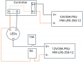
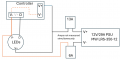
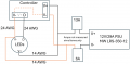
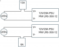
I suspect this is a pretty basic question but I couldn't find anything on the web. I have a VERY basic circuit which consists of a 12V DC PSU and a whole bunch of LEDs in series. I wanted to figure out how many amps are being pulled so I put an amp meter between V+ and the beginning of the LED array. It showed me 13A. Later on, I happened to measure the amperage between V- and the end of the LED array. To my surprise it showed less than half of what I measured before, i.e. 6A. See the attached image. I don't understand why that is happening. Electrons aren't being destroyed, it's only the voltage that drops over each of the LEDs. So in this very simple circuit, it shouldn't matter where I measure the current.

Note that these LEDs are "pixels" that have a data line. The data line tells them what color should be displayed and at what brightness. For this experiment, in both cases where I measured the current, the LEDs were set to white with 100% intensity. I don't quite see how this could influence the current based on where I measure. But maybe I am missing something.
 

Attachments

WBahn

Joined Mar 31, 2012
32,746
My guess (and that's what it is) is that the circuitry that controls the brightness is referenced to V- of the supply (via the data lines) and so by placing the meter in the V- side, it raises the voltage at the bottom of the LEDs such that the same commanded output actually results in less output. Humans tend to be pretty insensitive to a change in light intensity of a factor of two, so you might well not notice that the light output has been cut in half, but if you use a light meter, that should tell you whether this is actually happening.

If you have a second ammeter, put one in each path and you should then see the same current draw (allowing for whatever mismatch is associated with current in your data lines, which I wouldn't think would be very much).

Another test you could perform would be to leave your meter in the V+ line and then see what effect adding resistance in the V- line has on the current draw. Again, a second meter can really help out here. First, put the ammeter in the V- line and measure the voltage drop across the meter with a voltmeter. Then get a resistor (or a bunch of resistors together -- take power dissipation into account!) that will drop that voltage at that current. Then, with the ammeter back in the V+ line, see if inserting that resistor instead of the meter results in the lower current draw. You can then, if interested, map out the effect by putting different resistor values (say half and one-quarter and one-tenth) in the V- line and see if the current moves upward accordingly.
 

LowQCab

Joined Nov 6, 2012
5,101
You must have an accurate Schematic that shows ALL connections to make it
possible to determine exactly what You are measuring.

A continuous "Circuit" will have exactly the same amount of Current flowing at any given point,
unless, of course,
the "Circuit" is not actually a single continuous Circuit,
but has been broken into separate sections, which You are measuring separately.
.
.
.
 

WBahn

Joined Mar 31, 2012
32,746
But his two measurements are not in the same circuit. By moving the meter, he is making two different current measurements in two different circuits. There's no reason for them to be the same unless the assumption that the current meter is ideal is sufficiently valid, which requires that the meter burden voltage has an acceptably-negligible impact on the circuit. I suspect that the most-likely explanation for what he is seeing is that this assumption isn't valid in this case. But without more detail, either of the circuit or of more focused measurements, it's impossible to say for sure.
 

Thread Starter

mulu

Joined Aug 4, 2024
16
Ok, I think I see what is going on. The LEDs are powered by the PSU as shown before. I didn't think the controller would have an influence so I just mentioned it but didn't include it in the drawing. But that controller seems the key point. The controller was powered by the same PSU as the LEDs. From the controller, I took V- and D (data) to the LEDs. I also took V- from the PSU to the V- port on the LEDs. The V+ on the controller was not used. Instead, I took V+ directly from the PSU to the LEDs.

In my initial post, I temporarily used just one PSU for debugging purposes. Attached is what actually the final goal is, i.e. there will be two PSUs. One to power the controller (I used a 12V/29A meanwell but it will be replaced with a smaller one). Then power for the LEDs comes from a separate PSU. One or two PSUs, the issue seems the same, i.e. there are TWO paths current can take from the V- port on the LEDs. It can either go through the wire where I measure the 6A (to the PSU that powers the LEDs) or it can go through the V- on the controller.

So that explains the measurement. Now I wonder, if all of this could cause grounding issues. I have issues where the LEDs are flickering. Maybe that's the reason. Btw, the flickering also happens when I use just one PSU.
 

Attachments

WBahn

Joined Mar 31, 2012
32,746
1731521127383.png

Now THIS makes ZERO sense.

Are you really saying that you measured 13 A in the V+ line and 6 A in the V- line of that bottom supply AT THE SAME TIME? As in, you had TWO meters, one each line, and one was displaying 13 A at the exact same time that the other was displaying 6 A?
 

Thread Starter

mulu

Joined Aug 4, 2024
16
Sorry, for the confusion. I just meant to indicate where I measured. I didn't measure at the same time. I only have one multimeter which is why I could do the tests that you mentioned in your first replay. So I first measured on the V+ line and got 13A. Then I took the multimeter off, made a straight connection from the V+ on the PSU to the LEDs and then inserted the multimeter on the V- line. There I measured 6A.
 

Tonyr1084

Joined Sep 24, 2015
9,744
A continuous "Circuit" will have exactly the same amount of Current flowing at any given point, unless, of course, the "Circuit" is not actually a single continuous Circuit, but has been broken into separate sections, which You are measuring separately.
This is what I was going to say. In my own vernacular, 'The current will be the same throughout the whole circuit.' If you are legitimately finding two different amperage ratings then it must have something to do with the connections OR the voltage from the PSU is changing.

At first I thought you had a 12 volt battery. IF THAT'S THE CASE then as the voltage drops the current will drop too. It's possible in my mind that the voltage has dropped significantly between the times you tested on the positive leg and testing on the negative lead.

Regardless, something changed between the 13A and the 6A readings.
 

Tonyr1084

Joined Sep 24, 2015
9,744
I suspect that the most-likely explanation for what he is seeing is that this assumption isn't valid in this case.
OR it's possible the meter was not set up the same way for each measurement. I'm not saying the TS made a mistake, but I look back on my own history - I've done exactly that in the past. Setup is important. But to have the same exact setup and the same exact everything - the amperage should also be the same.
The controller was powered by the same PSU as the LEDs. From the controller, I took V- and D (data) to the LEDs. I also took V- from the PSU to the V- port on the LEDs.
Something I'm just now considering is the D line. Are the LED's addressable? Color changing? If so then if the color or pattern of LED's are changed then that would account for some variability in the amperage. Don't know if it would account for that big a change, but I'd assume that as another possibility.

So are these addressable?
Are these color changing?
 

WBahn

Joined Mar 31, 2012
32,746
Sorry, for the confusion. I just meant to indicate where I measured. I didn't measure at the same time. I only have one multimeter which is why I could do the tests that you mentioned in your first replay. So I first measured on the V+ line and got 13A. Then I took the multimeter off, made a straight connection from the V+ on the PSU to the LEDs and then inserted the multimeter on the V- line. There I measured 6A.
Do you have the specs on the meter? If so, what is the burden voltage on the range you are using? If you have the meter make and model, we might be able to find the info online.

Do you have any power resistors available to experiment with?
 

Thread Starter

mulu

Joined Aug 4, 2024
16
Yes, these are addressable and color changing LEDs. For this testing, I always have all the LEDs on white at 100%.

The meter I have is a Voltcraft M-3850. The only power resistor I have is a 10 ohm/10W. All others are 1/8W, 1/4W and a few 1W.

Having said that, do you think the issue is that the V- port at the end of the chain of LEDs sends current down where I have my meter and some back to the controller? These are the orange paths in the image in my post #5 (note I don't measure current at these two positions at the same time but one after the other).
 

ElectricSpidey

Joined Dec 2, 2017
3,316
I'm just curious...do you have the controller/supply connected to one end of the string and the second supply connected at the other end?

And no positive connected at the controller end?
 

WBahn

Joined Mar 31, 2012
32,746
Yes, these are addressable and color changing LEDs. For this testing, I always have all the LEDs on white at 100%.

The meter I have is a Voltcraft M-3850. The only power resistor I have is a 10 ohm/10W. All others are 1/8W, 1/4W and a few 1W.

Having said that, do you think the issue is that the V- port at the end of the chain of LEDs sends current down where I have my meter and some back to the controller? These are the orange paths in the image in my post #5 (note I don't measure current at these two positions at the same time but one after the other).
I haven't been able to track down the burden voltage on that meter. This is basically a rebranded Metex meter and, like most lower-end meters, they don't seem to feel any need to publish meaningful spec information.

I'm guessing (and that's all it is) that the voltage drop across your meter is going to be in the 100 mV to 500 mV range, so you would need something like 50 mΩ to 100 mΩ at a couple of watts. Probably on the lower end of things, actually, so maybe more like 10 mΩ and 250 mW. So see about combining a bunch of your resistors in parallel to get down into the 10 mΩ to 100 mΩ range.

While there is the possibility for some ground loop current interaction between your supplies, it is unlikely that it could account for this kind of discrepancy.

The main cause still seems, to me, to be that the presence of the meter in the V- leg is affecting the control functionality such that "100%" output is only about half the output when the meter is present compared to when it isn't.

Try this. Put the meter in the V- leg and set up a jump so that you can easy short and unshort the meter. Then look at the light (or, if it's too bright, shine it onto a piece of paper and look at the paper and, while looking at the light continuously, go back and forth between the meter being shorted and not, say about once or twice per second, and see if you perceive a fluctuation in brightness.
 

Thread Starter

mulu

Joined Aug 4, 2024
16
I'm just curious...do you have the controller/supply connected to one end of the string and the second supply connected at the other end?
And no positive connected at the controller end?
Eventually, I probably will have more power injected from the other side of the string. But as of now, V-, V+ and D are all fed from just one side of the LED string.

The controller has V-, V+ and D outputs. V+ is not being used. I am just using the V- and D output of the controller. V- and D go to the LED string via a twisted cable. Then V- from the (other) PSU is combined with the V- from the controller relatively close (around 2' due to the LED pigtails) to the first pixel. Attached is the drawing of the setup I use for all things I posted here. The drawing in #5 is what I will do next (again) after I figured out the discrepancy between the 13A on V+ and 6A on V-.
 

Attachments

LesJones

Joined Jan 8, 2017
4,511
Re post #6. So you are powering the system with TWO POWER SUPPLIES. One for the controller and one for the group of LEDs. I think there is a good chance that there is not true isolation between the two power supplies. I suspect that the negative of the power supplies may be connected to mains earth. If this is the case the negative terminals of the power supplies will be connected together. this would mean that the meter was not reading the total current to the negative of the LEDs (Part of the current could be passing through the negative lead supplying the controller by the path provided by through mains earth connection between the supplies.)

Les.
 
Last edited:

Thread Starter

mulu

Joined Aug 4, 2024
16
Re post #6. So you are powering the system with TWO POWER SUPPLIES. One for the controller and one for the group of LEDs. I think there is a good chance that there is not true isolation between the two power supplies. I suspect that the negative of the power supplies may be connected to mains earth. If this is the case the negative terminals of the power supplies will be connected together. this would mean that the meter was not reading the total current to the negative of the LEDs (Part of the current could be passing through the negative lead supplying the controller by the path provided by through mains earth connection between the supplies.)
Les.
Post #6 is what I initially had (before posting here) and what my final goal is. But before posting here, I simplified the setup. All posts are for what I show in post #14 with just one PSU.
 

Tonyr1084

Joined Sep 24, 2015
9,744
If your controller has V+, V- & D then connect just the controller to the LED's and see what you get. I'm betting you get a balanced current load, now that I've read
So you are powering the system with TWO POWER SUPPLIES. One for the controller and one for the group of LEDs. I think there is a good chance that there is not true isolation between the two power supplies. I suspect that the negative of the power supplies may be connected to mains earth. If this is the case the negative terminals of the power supplies will be connected together. this would mean that the meter was not reading the total current to the negative of the LEDs (Part of the current could be passing through the negative lead supplying the controller by the path provided by through mains earth connection between the supplies.)
So why do you need two separate power sources? I know one is the controller, but that should be the - um - controller (?) of the whole string?

Are you adding extra strings? More strings than is recommended for the controller?
 

Thread Starter

mulu

Joined Aug 4, 2024
16
When I disconnect V- from the controller, I indeed get 13A on V-. However, now all the LEDs are flickering. I believe this is because the data doesn't have a reference/V- anymore. So I think I do need that path. There is a pretty good amount of current flowing, though so I am a bit concerned the return can take two paths.

In any case, the reason I use a second PSU is because of voltage loss. The controller is somewhat far from the LEDs. The distance isn't much of an issue for the data line. However, it is for the power, even with 14AWG pure copper cable. So I am bringing the power supply closer to the LEDs. But now if the current from V- on the LEDs can go back through the controller, it will take that longer route.
 

Tonyr1084

Joined Sep 24, 2015
9,744
OK, so I'm going to say it - - - 13 amps? Why so high? The whole thing about LED's is their far lower current consumption. I'm not there to take the measurements but I'm having a little trouble imagining 13 amps on an LED circuit.
 

Thread Starter

mulu

Joined Aug 4, 2024
16
The controller actually has 4 ports. Each port controls 1 matrix of 400 seed pixels. The pixels in a matrix are arranged in series. Each matrix of 400 pixels pulls ~3.4A, hence a total of about 13A. At 13A there is going to be a considerable voltage drop over longer distance, even with 14 AWG pure copper cables. Hence, I need to bring the PSU closer to the LEDs/pixels.

With this current, I am a bit concerned that about half of the current goes to the controller and from there to the PSU that powers the controller. So for one matrix it's actually "only" 3.4A. So half of that goes back over the thick 14AWG cable. The other half, i.e. some 1.7A goes back over the 24 AWG V- cable to the controller (I am using twisted pair CAT6 cable). 24AWG should be good for 1.6A for 4 cores (there are 4 V- and 4 D conductors per CAT cable, serving the 4 ports on the controller). So if 1.7A goes back through that cable, I am pushing it to the absolute max which concerns me.
 

Attachments

Top