Facebook
 Google
 GitHub
 Linkedin
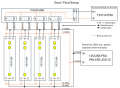
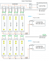
@wraujr I will give this a try. Though, usually people who do this kind of stuff provide power both on the side where the data is coming and tie the V- from the PSU with the V- from the controller. Then they power inject from the other side as in your corrected drawing. I am not saying what that community does is correct but that is how most seem to be doing it.
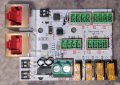
@MisterBill2 Attached is an image of the controller. It has some chips on it which I assume(!) require power from that big green terminal. On the controller, the GND and V is also connected to the G and V on the 4 green ports. I don't use the V on those 4 green port, though. That's to avoid voltage drop between the controller and the LED strip (the controller is further away than the PSU).
@MisterBill2 Attached is an image of the controller. It has some chips on it which I assume(!) require power from that big green terminal. On the controller, the GND and V is also connected to the G and V on the 4 green ports. I don't use the V on those 4 green port, though. That's to avoid voltage drop between the controller and the LED strip (the controller is further away than the PSU).
Attachments
-
 259.9 KB Views: 8