Your calculations for the combined resistance are correct.
I'm not sure about the table at the top right.
Firstly, you seem to have written mA next to the value that you calculated in Amps.
Secondly, the current through R4 isn't the same as the current through R1.
The circuit is supposed to be mA, i thought moving the decimal would make it into Amps. So i left it as it was calculated. Adding another picture. I Definitely got everything wrong excpt for the Total R, and R1 Volts.
I really did R1 and R4 using I =E/R and got R1 0.091984127
R4 0.091993127
What you have written there is 92μA which is wrong.
You will make fewer mistakes if you always work in the base units: Volt. Amp, Watt etc. and only convert to m, k or μ after you get the final answer in standard form.
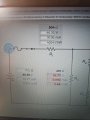
It's hard to tell what your starting point was and what you are being asked to solve. I'm assuming that you were given a circuit and the voltage of the voltage source (though 65.55 V is a bit of an odd value) and the values of each of the resistors. Is that correct?
I'm also assuming that your table in the upper left is what you were asked to do, namely find the voltage across, current through, and power dissipated in each resistor?
If so, then that table should be at the bottom of your work -- your work should progress like a novel, from top to bottom. You also need to look at your answers and ask if they make sense.
You are claiming that the total current is 92 mA (at least, that's what I'm assuming you meant, and not 92 µA, which is what you actually have written). But if that's the current in R1, how can that current split among the two branches (R4 in one branch and R2,R3 in the other) and still be 92 mA in each branch?
Also, if the total power is 6.08 mW, then how can the sum of the power in the resistors total over 12 mW?
Also, how can the sum of the voltage across R2 and R3 be over 60 V when the voltage across R4, which is in parallel with it, be less than 27 V?
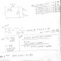
Further, you need to start tracking your units throughout your work -- at each and every step. This will catch the vast majority of mistakes that you will make -- and you WILL make them, we all do. It will also help prevent you from being three orders of magnitude off, which is what you have done with your currents in your table.
In addition, you calculated the power and then just tacked on the unit, mW, that you thought the answer should have, which again through your answer off by three orders of magnitude. 65 V across 705 Ω is 6 W, not 6 mW. Track your units!
Thank you both, I was able to see the mistakes.
65.55V ÷ 705R=0.09297823, covert by moving decimal 3 spaces right 92.97mA .
65.55V×92.97mA =6094.1835mW drop number after decimal for correct mW.
Total
705R
65.55V
92.97mA
6092mW
Now thats corrected, I should be able to find the components correctly.
It's hard to tell what your starting point was and what you are being asked to solve. I'm assuming that you were given a circuit and the voltage of the voltage source (though 65.55 V is a bit of an odd value) and the values of each of the resistors. Is that correct?
I'm also assuming that your table in the upper left is what you were asked to do, namely find the voltage across, current through, and power dissipated in each resistor?
If so, then that table should be at the bottom of your work -- your work should progress like a novel, from top to bottom. You also need to look at your answers and ask if they make sense.
You are claiming that the total current is 92 mA (at least, that's what I'm assuming you meant, and not 92 µA, which is what you actually have written). But if that's the current in R1, how can that current split among the two branches (R4 in one branch and R2,R3 in the other) and still be 92 mA in each branch?
Also, if the total power is 6.08 mW, then how can the sum of the power in the resistors total over 12 mW?
Also, how can the sum of the voltage across R2 and R3 be over 60 V when the voltage across R4, which is in parallel with it, be less than 27 V?
Further, you need to start tracking your units throughout your work -- at each and every step. This will catch the vast majority of mistakes that you will make -- and you WILL make them, we all do. It will also help prevent you from being three orders of magnitude off, which is what you have done with your currents in your table.
In addition, you calculated the power and then just tacked on the unit, mW, that you thought the answer should have, which again through your answer off by three orders of magnitude. 65 V across 705 Ω is 6 W, not 6 mW. Track your units!
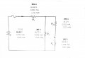
You know the combined value of R2,R3 and R4, and the current that flows through them collectively as a series-parallel combination.
So you know the voltage across the combination, which is also the voltage across R4
So you can work out the current through R4.
Then you can work out the current through R2 and R3.
Then you can work out the voltage across R2, and the voltage across R3.
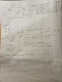
I've attached one suggestion on how I would recommend doing, and showing, your work.
Notice that I carried my intermediate results to five sig figs. This gives me cushion for round off error so that my results, which are generally reported to three sig figs, will be good since cumulative round off errors seldom propagate more than one sig fig from the starting values.
Also notice that I did the scaling prefix conversions explicitly when calculating I_T and V_1. Do this until you get very comfortable with them. I did them implicitly from that point on.
Finally, notice the checks at the end. These are extremely important. Find as many ways to verify the correctness of your answers. In an academic setting, it will significantly improve your grades. In the real world, it will keep you from it will help you catch mistakes that will otherwise cost money, damaged equipment, lost contracts, injuries, or even deaths. Remember, if a doctor makes a mistake they can kill some one. But doctors generally kill people one at a time, while engineers kill people in job lots.
In doing my last check, I got I_2 + I_4 = 92.924 mA, which does not compare as close as it should with I_1 = 92.877 mA. It's close, but further away than it should be. The total power check also showed a discrepancy larger than I expected, 6.0881 W vs. 6.0890 W, and did get noticed, but I convinced myself that this was close enough to be round-off error.
So I went back and looked at me work and discovered that I had written down that V_1 was 46.801 V instead of 46.810 V. Just a transcription error from the calculator to paper. It happened to be minor, but what if I had written down 46.810 V instead. That would have introduced a more significant error that would definitely been seen in my final results reported to three sig figs. Because the work is well presented and organized, I was able to go back through and correct all of the results in just a few minutes.
I would have caught this mistake earlier had I done this check as soon as I had all three numbers. In fact, I did do it mentally, but I'm only looking for agreement to a couple sig figs in order to catch major mistakes. Minor mistakes slip past that and need the additional fine checks at the end.
In fixing the earlier mistake, I made another mistake in the P_2 calculation (fat fingered the calculator and got a slightly lower result), but the total power check caught that easily.
This is just proof that mistakes are not limited to students or those that lack experience. We all make them and we make them on a surprisingly regular basis. So you need to find ways to constantly be checking yourself.
Another note on units tracking. It's not a matter of just tacking the units on. It's a matter of treating them like the mathematical quantity that they are. When two things are added, the units must agree. When they are multiplied or divided, the new units must match the multiplication or division of the units. So if you are dividing a voltage by a current, don't just write down Ω because you are calculating a resistance. Ask yourself what V/A is. I picture, in my mind, Ohm's Law and I say to myself "V=I·R, so R = V/I." Even after nearly half a century of working with this stuff, I still do that almost every time. Units tracking is probably the single most powerful error-detection tool available to the engineer, but only if it is used diligently, consistently, and properly. Most (but certainly not all) mistakes that you make will mess up the units, so you need them there in order for them to get messed up. The good news is that it takes a surprisingly short amount of time before you will do it without thinking about it and it will even get to the point where you can't work problems that don't have proper units and you will find yourself consciously putting in the proper units so that you can work the problem.
The second most powerful error-detection tool is to always ask yourself if the answer makes sense.
I'll never forget why my Intermediate Electricity and Magnetism professor (who eventually became the president of the university) said to us the first day of class: "There's one thing that separates you and me from Nobel Prize winning physicists. The people walking across that stage religiously do two things: They always, always, always track their units, and they always, always, always ask if the answer makes sense."
That is perhaps the single best advice I received as an college student, and applying it took me from getting 3.5 semester GPAs to 4.0s, not to mention greatly enhancing the quality of my work as a design engineer.
 Facebook
 Google
 GitHub
 Linkedin
 2.3 MB Views: 20