Facebook
 Google
 GitHub
 Linkedin
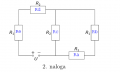
I need to solve this circuit. R1 resistors have 1 kiloohms resistance and R2 have 4 kiloohms. What is the equivalent resistance of the resistors in the circuit in the figure? What is the current flowing in the individual branches, if the driving voltage of the galvanic cell is 12V?

Last edited by a moderator: