Thank you for the confirmation, when injecting voltage because I don’t currently have freezer electronic spray could I use IPA instead to find the the component that heats up more than the rest?
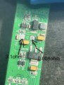
Here is the circuit diagram... D2 is there to protect against reversed battery - it should blow an input fuse rather than die itself... so the question is, how did the battery get reversed (and why was there no fuse)???
There's a good chance U3 is dead, if the 12v input is showing 3.1ohm to ground... and C16/C17 are OK.
Thank you, I have soldered the black wire to ground and red wire to 12v but when I checked for continuity to make sure they were soldered on properly both the ground and 12v get continuity through the black wire, is this how it should be or should the 12v be getting continuity through the red wire as the red wire is the one going to the 12v?
Thank you, I have soldered the black wire to ground and red wire to 12v but when I checked for continuity to make sure they were soldered on properly both the ground and 12v get continuity through the black wire, is this how it should be or should the 12v be getting continuity through the red wire as the red wire is the one going to the 12v?
Not sure I understand what you're trying to say. Do you mean there is continuity from red to black? Given you measured 3ohm between the top of D2, which is +12v, and ground earlier, there will be continuity between red and black - that's the short we're trying to identify.
Not sure I understand what you're trying to say. Do you mean there is continuity from red to black? Given you measured 3ohm between the top of D2, which is +12v, and ground earlier, there will be continuity between red and black - that's the short we're trying to identify.
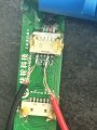
Now the cable is unplugged the short to ground is gone and on the other end of that cable is this board in the image so would it be something to do with this board?
I tested D2 out of circuit and that was faulty yes but now I’ve unplugged that other board the short to ground has gone so that means the fault is being caused by something on the second board I sent right? But I have tested the caps and none of them are shorted or anything so I’m unsure what to test for next
I'm confused... the cable in the pic above, with no connector on it, was connected to the board you thought was faulty? How is this board connected to the other unit you just showed. Can you show a pic of them altogether, or draw a sketch. Where does the 12v come from?
So the connector in my hand connects to the first board that had the short to ground when plugged in and then the wire goes through the stem to the second board in the black block and then comes back out on another wire that I desoldered off the motor on the front wheel
OK, and the wire you desoldered is that one in the bottom left of this pic and the same as the one in post #30?
Where does the power for all this come from and how does it get there...?
If D2 did fail due a supply reversal, and this board survived (which isn't guaranteed) then there's likely to be a catastrophic failure on the other board.
What actually happened to cause this problem?
Assuming there's nothing missing on the original board except D2, you could test that in isolation by applying 12v to the red & black wires. Put it on a low current limit first, say 100mA, though with nothing else plugged in it shouldn't take much current, maybe 20 or 30mA. If it seems ok, check the 5v and 3.3v outputs at C8 and C6.
 Facebook
 Google
 GitHub
 Linkedin