Facebook
 Google
 GitHub
 Linkedin
I have what seems to be a very well built PSU meant for Cisco switches.It has 42v, 12v, and 3.3v outputs
I have a number of these supplies and would like to know if anyone may have some insight on how to determine which wire does what - such as a remote power on, a line that detects a load, etc. I've modded a lot PC and server PSU's but they were a little more straight forward than this. I have looked for a wiring diagram but found none.
The model is "cisco Milan Plus AC/DC) P/N 34-1535-02
Another model/manufacturer name may ArtesynP/N 7000056-0002
This device does 27.5/55.5A@42v (120 vs 240VAC)
- 12A @ 12v (120 & 240vac)
- 5A @5v (120 & 240vac)
- 15A @ 3.3v (120 & 240vac)
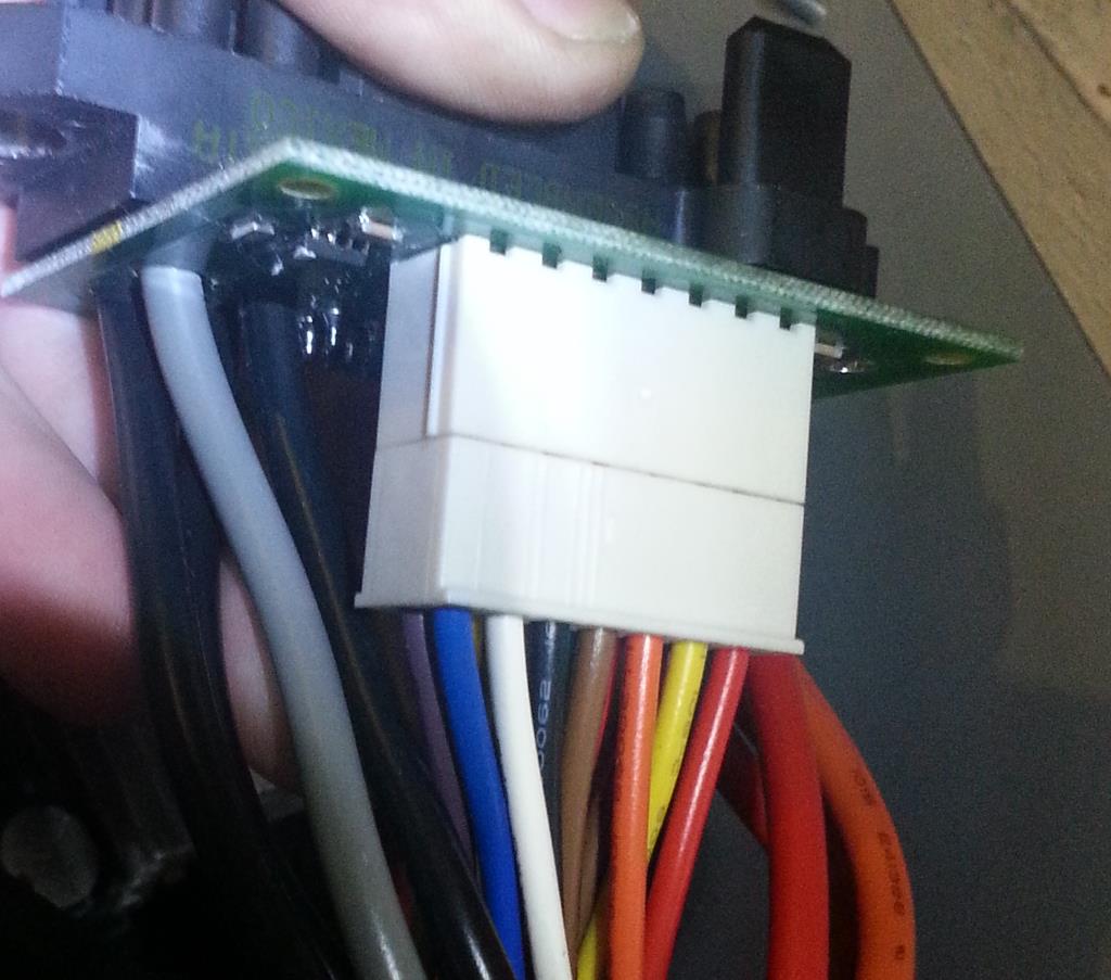
The 8 large wires on either side of the 14 pin connector are all directly soldered onto the PCB. The 14 pin (output) connector is connected to the main PCB
When I plug it in I get a green light on the fan light and the input or output do not come up as failed. I think it is jut not sensing a load or equipment attached so it isn't getting past the "pre-boot".
Does anyone have any ideas as to how I might go about figuring out which wire on the 14 pin does what? I am pretty sure on the red, orange,yellow and blacks (but could be mistaken).
I think I have access to the units this plugs into if that would help determine what the pins are.
I can post more pics if needed. Thanks for any insight on this matter!
Output connections
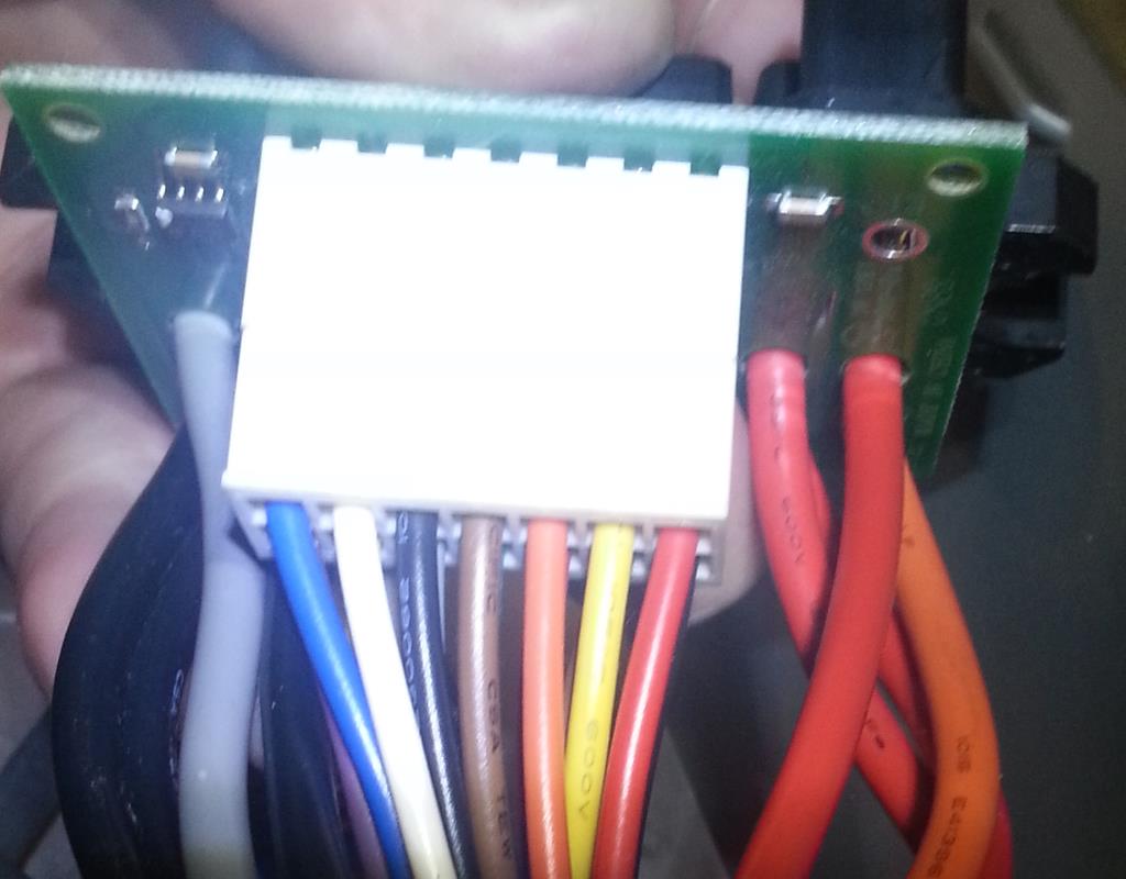
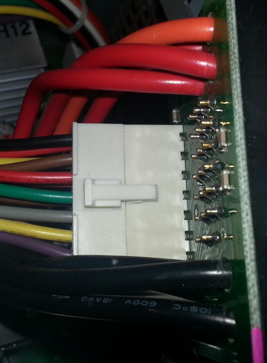
Connection to main PCB


I have a number of these supplies and would like to know if anyone may have some insight on how to determine which wire does what - such as a remote power on, a line that detects a load, etc. I've modded a lot PC and server PSU's but they were a little more straight forward than this. I have looked for a wiring diagram but found none.
The model is "cisco Milan Plus AC/DC) P/N 34-1535-02
Another model/manufacturer name may ArtesynP/N 7000056-0002
This device does 27.5/55.5A@42v (120 vs 240VAC)
- 12A @ 12v (120 & 240vac)
- 5A @5v (120 & 240vac)
- 15A @ 3.3v (120 & 240vac)
The 8 large wires on either side of the 14 pin connector are all directly soldered onto the PCB. The 14 pin (output) connector is connected to the main PCB
When I plug it in I get a green light on the fan light and the input or output do not come up as failed. I think it is jut not sensing a load or equipment attached so it isn't getting past the "pre-boot".
Does anyone have any ideas as to how I might go about figuring out which wire on the 14 pin does what? I am pretty sure on the red, orange,yellow and blacks (but could be mistaken).
I think I have access to the units this plugs into if that would help determine what the pins are.
I can post more pics if needed. Thanks for any insight on this matter!
Output connections
Connection to main PCB