Determining Pin out on connector to a CCD camera

Thread Starter

gdcookuk

Joined Feb 20, 2019
4
Hi

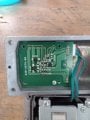
I have a Camera that has a 5 pin mini din connector. (Clarion CC-2002E narrow angle reverse camera)

It should have 9 volts powering it and output a Video signal.

How would I go about determining the what pins what? Is it possible using a multimeter to at least work out the positive in and ground Pins?

Any help appreciated.

Thanks
 

pmd34

Joined Feb 22, 2014
527
If you cant find a pdf online somewhere showing the connections. The easiest way would be to take the housing off the camera and look inside. The 0V of the power supply will go to the ground of the circuit board, screw fixings etc. The +9V will usually go to the + side of some of the largest capacitors in the camera (and manufacturer actually do tend to use red for this wire anyhow!) The video output is likely to be a coax cable, with shield connected to 0V and the connections to the center should stand out from the other PCB traces.
 

Thread Starter

gdcookuk

Joined Feb 20, 2019
4
Thanks for your response.

I couldn't find any info online unfortunately.
However I followed your advice and looked inside the camera.

I was unable to identify anything that look like large capacitors to me. Or indeed the ground!!! But I was able to identify the Video and shield. This left a red , a black and a blue wire.

I then tested for continuity between the pin outs on the connector. Once I established this I put nine volts across the Red and black (assuming that this was the positive and ground) then measured a small voltage (less than 1 volt) at the centre of the coax.

Do you know if I have made the assumptions correctly about the red and black wires that from the video coax you would see approximately this reading?
 

pmd34

Joined Feb 22, 2014
527
Hi gdcook, im afraid I dont really know much about TV signal voltages etc. if you could send a photo of the PCB i could try and see if I can make any sense of it?
 

pmd34

Joined Feb 22, 2014
527
Hi gdcookuk, hmm not much to go on on that PCB at all as, you say! I think you discovered all there was. The way the red and black wire are glued together does suggest they are the power supply. The white and black belong together so seems fair they are the signal... that just leaves the blue...

I saw that "clarion" have some system for activating the camera when you put your car in revers gear:
https://www.clarion.com/au/en/pdf/CAA185_Manual.pdf

So the blue could be an input to wake the camera and switch on the signal. But it's a bit risky putting voltage down it unknown!
You could TRY and trace the blue wire back to the other circuit board in the camera and see if it goes to anything obvious, like an opto isolator etc. I am more inclined to believe that it would be for a 5V signal, but....
 

Thread Starter

gdcookuk

Joined Feb 20, 2019
4
Thanks hadn't seen that pdf before. Looks like the camera needs 12volts from the accessory circuit. And also 12 volts from the reverse lights circuit. So the blue wire may as you suggested wake it up. I might give it ago, under that assumption. If it gets fried so be it. Was cheap off eBay and the narrow angle cameras are normally expensive so thought I would gamble. I let you know how I go. Thanks for your help.

It's been useful.
 

pmd34

Joined Feb 22, 2014
527
I dont know if that power supply box was for the same camera actually... also it is possible the box had a 12V to 5V signal converter.

If you test the blue wire, I would start with 5V and put in a series resistor to limit the current to a few mA so if it is not correct there is not enough power to do any serious damage.
 
Top