Facebook
 Google
 GitHub
 Linkedin
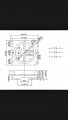
Hello all, I need help, I'm not sure how to wire up my ring led in a series of a curved led strip, I'm using a cad program to design my own PCI board but I'm not sure how my smd 5050 LEDs wire up. Ik for every three LEDs I need a 22ohm resistor because my LEDs max power is 3.6 volts. I bought a rgb controller and it has four pins. One fire red green blue and positive. But I'm not sure exactly how to design my board. Like idk what connections to wire up. I'm new here so I'm not real fimilar with how to these LEDs need to be wired with the PCB board. If anyone knows how or has a disgram or any advice. Throw it my way... Thanks you
Attachments
-
 150.3 KB Views: 30
 -
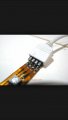 69.5 KB Views: 33
 -
 138.7 KB Views: 38