PCB Board troubleshoot.. running with no errors, but need review - *new to designing*

Thread Starter

ASTRO_1994

Joined Jul 31, 2024
7
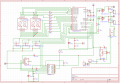
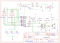
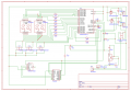
I'm attempting to design a countdown timer that has 2 external 12v motors connected.
I've added the usb type c connector and the usb converter to upload and edit code after printing board.
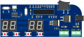
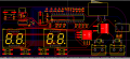
the 3 buttons control the up/down/set of the timer and the 4th button is an override switch to supply both motors power when pressed.
The dual 7 segment display counts down duration on one side and frequency on the other for when both motors are active. (00-00)
I've run it without errors, but I'm also quite novice in this field - looking for critiquing - thanks!
 

Attachments

ronsimpson

Joined Oct 7, 2019
4,646
On the MOSFETs the Gate and Drain are mixed up. Gate goes to resistor then to micro.
Something is wrong with C3. It looks like a short.
Microcomputer reset pin. 10k pullup. What is the 18pF cap doing?
 

Jon Chandler

Joined Jun 12, 2008
1,560
The CH340G needs a capacitor on V3. Check the datasheet for the value.

The CH340G also needs a 12 MHz crystal and 22pF caps.

The CH340 and micro need 100 nF bypass caps close to the power pins.

Does the micro need caps for its crystal?

Micro Tx --> CH340 Rx
Micro Rx --> CH340 Tx

Power Issue:

Vcc comes from USB connector and goes to micro Vcc

AVcc comes from voltage regulator to micro AVcc input.

Micro will not be properly powered if USB not connected or if AVcc power is not connected.
 

ronsimpson

Joined Oct 7, 2019
4,646
Any time you do a USB data look at the data sheet for layout. If they don't have it look at another USB part. The D+ and D- lines need to be very short. Keep the line length the same.
 

Jon Chandler

Joined Jun 12, 2008
1,560
The CH340 part looks correct.

Check the micro datasheet regarding Vcc and AVcc connections, and the caps you have shown. There should be a 100nF bypass cap between Vcc and ground, and there may be recommendations around AVcc.

Do note – the parts of the circuit I have commented on are the parts I looked at. I'm not saying there are or aren't other problems.
 

Jon Chandler

Joined Jun 12, 2008
1,560
Does the micro have internal pullups for the switches? If not, add 10k pullup resistors to Vcc for each one.

Conventionally, ground symbols ALWAYS point DOWN. Your schematic will be easier to understand if you use EasyEDA's +Vcc or +5V symbols, which always point up. All points with a +5V symbol will be connected in the net list, so you don't have to follow long lines all over to see what's what.
 

Thread Starter

ASTRO_1994

Joined Jul 31, 2024
7
Back after a bit of a leave with good and bad news..

Good: the printed circuit board operates the 2 motors on an override switch (SW2) when connected to 12v power supply.

Bad: the micro, usb, and display functions are unresponsive.

Attached are the schematic file, PCB layout, and 3D view. Before throwing the baby out with the bath water, I'm attempting to see if the micro simply needs to be flashed to work, however due to my lack of experience I'm leaning towards the fact it may be more likely caused by a wiring issue, and will require a reprint..

To reiterate - the circuit should function as follows:

- 12v in operated by a rocker switch (SW1).
- When ON the override switch (SW2) controls both motors simultaneously (working at the moment).
- The micro should also receive power when SW1 is ON and allow SW3, SW4, and SW5 to operate the display (not working).
- When the board is connected via usb to computer it's recognizing the CH340, but not the atmega and it's unable to be programmed.

Any further review is much appreciated - thanks in advance!
 

Attachments

Thread Starter

ASTRO_1994

Joined Jul 31, 2024
7
@Jon Chandler @ronsimpson
Back after a bit of a leave with good and bad news..

Good: the printed circuit board operates the 2 motors on an override switch (SW2) when connected to 12v power supply.

Bad: the micro, usb, and display functions are unresponsive.

Attached are the schematic file, PCB layout, and 3D view. Before throwing the baby out with the bath water, I'm attempting to see if the micro simply needs to be flashed to work, however due to my lack of experience I'm leaning towards the fact it may be more likely caused by a wiring issue, and will require a reprint..

To reiterate - the circuit should function as follows:

- 12v in operated by a rocker switch (SW1).
- When ON the override switch (SW2) controls both motors simultaneously (working at the moment).
- The micro should also receive power when SW1 is ON and allow SW3, SW4, and SW5 to operate the display (not working).
- When the board is connected via usb to computer it's recognizing the CH340, but not the atmega and it's unable to be programmed.

Any further review is much appreciated - thanks in advance!
 
Top