Facebook
 Google
 GitHub
 Linkedin


Hi, I am designing smart LED light device that will be used outside. It will have a CPU (ESP32) and other components.
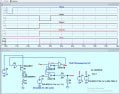
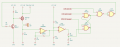
I want to design short circuit protection for LED (the circuit is below)
Requirements I have:
How it works:
The latch made from elements 74LS00 memorizes the state of short circuit.
Before switching LED on, CPU makes short low pulse to the latch input 4. Latch gets high in output 6. Now it is ready to switch the led on.
CPU then sends high signal to U2A input 1. Both high inputs gives LOW on U2A output and MOSFET switches on.
U1A - first stage of op amp amplifies normal LED current drop on R1 (~5 mV) 300 times. Let it be up to 2volts - I leave an error margin here. The version of LM358ADT has 2mV offset, I think it is OK for error margin.
U1B - the second stage compares the amplified voltage against a reference ~8V and if the first stage sends bigger voltage (due to short circuit, current shall rise few times, above 3-5 Amps), output of U1B goes low, latch output 6 goes low, gate U2A output goes high and it switches off the MOSFET
LED is switched off and U1B is high again. Without the latch, the power to the LED would be sent again. It would start to oscillate, but the latch remembers the state and power to the LED stays shut off.
CPU will receive HIGH level in "CPU LED shorted" input.
My questions:
Thank you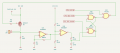
I want to design short circuit protection for LED (the circuit is below)
Requirements I have:
- High side switch (I want +12V to appear on LED only when it should)
- CPU gets notified if short circuit happens (there will be many such devices, I want to know which is faulty)
- Very low resistance shunt (R1 0,008 Ohm), because I do not want additional heat, as device will be packed in a hermetic box
How it works:
The latch made from elements 74LS00 memorizes the state of short circuit.
Before switching LED on, CPU makes short low pulse to the latch input 4. Latch gets high in output 6. Now it is ready to switch the led on.
CPU then sends high signal to U2A input 1. Both high inputs gives LOW on U2A output and MOSFET switches on.
U1A - first stage of op amp amplifies normal LED current drop on R1 (~5 mV) 300 times. Let it be up to 2volts - I leave an error margin here. The version of LM358ADT has 2mV offset, I think it is OK for error margin.
U1B - the second stage compares the amplified voltage against a reference ~8V and if the first stage sends bigger voltage (due to short circuit, current shall rise few times, above 3-5 Amps), output of U1B goes low, latch output 6 goes low, gate U2A output goes high and it switches off the MOSFET
LED is switched off and U1B is high again. Without the latch, the power to the LED would be sent again. It would start to oscillate, but the latch remembers the state and power to the LED stays shut off.
CPU will receive HIGH level in "CPU LED shorted" input.
My questions:
- Is it not overcomplicated?
- Will 2 stages of op amps be too slow? 74HC00 has nanosecond switching time, but LM358 sadly has ~25 microseconds per stage if I am correct.
- Are there any structural errors?
Thank you