Designing a short circuit protection

Thread Starter

rolandasg

Joined Oct 20, 2026
17
Hi, I am designing smart LED light device that will be used outside. It will have a CPU (ESP32) and other components.

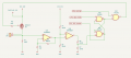
I want to design short circuit protection for LED (the circuit is below)

Requirements I have:

  • High side switch (I want +12V to appear on LED only when it should)
  • CPU gets notified if short circuit happens (there will be many such devices, I want to know which is faulty)
  • Very low resistance shunt (R1 0,008 Ohm), because I do not want additional heat, as device will be packed in a hermetic box

How it works:

The latch made from elements 74LS00 memorizes the state of short circuit.

Before switching LED on, CPU makes short low pulse to the latch input 4. Latch gets high in output 6. Now it is ready to switch the led on.

CPU then sends high signal to U2A input 1. Both high inputs gives LOW on U2A output and MOSFET switches on.

U1A - first stage of op amp amplifies normal LED current drop on R1 (~5 mV) 300 times. Let it be up to 2volts - I leave an error margin here. The version of LM358ADT has 2mV offset, I think it is OK for error margin.

U1B - the second stage compares the amplified voltage against a reference ~8V and if the first stage sends bigger voltage (due to short circuit, current shall rise few times, above 3-5 Amps), output of U1B goes low, latch output 6 goes low, gate U2A output goes high and it switches off the MOSFET

LED is switched off and U1B is high again. Without the latch, the power to the LED would be sent again. It would start to oscillate, but the latch remembers the state and power to the LED stays shut off.

CPU will receive HIGH level in "CPU LED shorted" input.

My questions:

  • Is it not overcomplicated?
  • Will 2 stages of op amps be too slow? 74HC00 has nanosecond switching time, but LM358 sadly has ~25 microseconds per stage if I am correct.
  • Are there any structural errors?

Thank youshort-circuit-protection.png
 

ericgibbs

Joined Jan 29, 2010
21,641
hi roland,
Welcome to AAC.
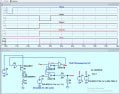
Have you calculated the Power PMOS Gate to Source voltages in the On/Off state of the 5V, 74LS00 drive output.?
EEG 2272.jpgEG 2275.jpg
 
Last edited:

Thread Starter

rolandasg

Joined Oct 20, 2026
17
hi roland,
Welcome to AAC.
Have you calculated the Power PMOS Gate to Source voltages in the On/Off state of the 5V, 74LS00 drive output.?
E
Hi, Thanks for your comment. If I understand your question correctly, you suggest P-MOSFET might not open or close fully? I do not know how to measure it, but I can place additional transistor between U2A and the gate of MOSFET.

Thank you!
 

ericgibbs

Joined Jan 29, 2010
21,641
hi roland,
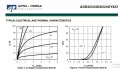
If you look at fig#2, I posted, you can see that MOSFET conduction occurs between -2V and -5V for Vgs.
Your circuit is switching between -7V and -12V, so the MOSFET is always conducting.

Redesign your circuit to the Vgs range shown fig #2.
E
 

Attachments

ericgibbs

Joined Jan 29, 2010
21,641
Hi rol,
What is the part number of the power LED.?

E

Update: @rolandasg
You could consider using a higher voltage working Logic IC range for your latch, example.. the HEF of CD4000 series.
 

Attachments

Last edited:

ericgibbs

Joined Jan 29, 2010
21,641
hi roland,
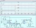
Use 12V for the CD4000 logic, and for the Shorted Signal the ESP32 a simple resistive divider.

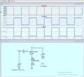
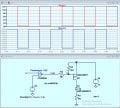
This LTSpice sim is of the Logic section.
Used a simple version of the LED and PMOS
E

@rolandasg
The LED is only 10Watt rating why are you using a high power PMOS FET???

EG 2280.jpg
 

Thread Starter

rolandasg

Joined Oct 20, 2026
17
Hi, nice, I have never considered logic series CD40xx.

I used such powerful mosfet because I wanted to avoid any heat. It is SMD package and I think putting it to PCB without any heatsink. Also, component selection options are not perfect in my area. So I found them for 0.5Euro and I was quite happy with them. P-mosfets are usually more expensive.

Rolandas
 

Thread Starter

rolandasg

Joined Oct 20, 2026
17
Hi r,
When you are ready, post your final circuit and I will try an LTSpice simulation.
E
Hey Eric,

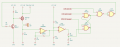
This is the second version below. I also exported netlist file from Kicad, as I have read it might help importing circuits into analysis tools

I did not use CD40xx for now. Not sure how it connects with ESP32, so went "classical" way. Also changed some pinouts for the latch. Also, added one more latch for inversion to feed NPN transistor. I am still not good at circuit design, so I just took pieces from the internet, and most common design is NPN+P mosfet :)

Thanks
Rolandasshort-circuit-protection-v2.png
 

Attachments

panic mode

Joined Oct 10, 2011
5,445
much better. this way Q2 is dealing with level shifting of one signal but your NAND gates can be low voltage so you do not have to translate levels on 3x CPU signals.

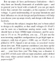
note that LM358 is a general purpose OpAmp and it is good for audio applications etc but not great for DC specially for signals near 0V (GND), unless you have the negative supply too. i would definitely not count on it for DC gain of 300 for input that is mere few mV, that would be job for precision opamp that also has rail to rail inputs. much better option would be to use actual current sense IC like ACS7xx or INA138 etc and have a cheap comparator... actually if you use current sensor ICs like mentioned, voltage levels would be significant (couple of volts) so U1B can stay as is working like comparator (real comparators are faster).
 
Last edited:

Thread Starter

rolandasg

Joined Oct 20, 2026
17
much better. this way Q2 is dealing with level shifting of one signal but your NAND gates can be low voltage so you do not have to translate levels on 3x CPU signals.

note that LM358 is a general purpose OpAmp and it is good for audio applications etc but not great for DC specially for signals near 0V (GND), unless you have the negative supply too. i would definitely not count on it for DC gain of 300 for input that is mere few mV, that would be job for precision opamp that also has rail to rail inputs. much better option would be to use actual current sense IC like ACS7xx or INA138 etc and have a cheap comparator... actually if you use current sensor ICs like mentioned, voltage levels would be significant (couple of volts) so U1B can stay as is working like comparator (real comparators are faster).
Thank you! I have read about INA138, nice thing! I need some time to try see how it would fit.
Btw, I think I was too optimistic about such a low shunt. I think i can increase it safely 5 times, giving it about 0,04 Ohm. Then I get 35-40mW max heat dissipation in "normal" mode (it will be a "sealed" box , IP65, so I do not want a lot of heat inside)
With that in mind - if I will also decrease amplification ratio 5 times in U1A - do you still think LM358 is a very poor choice, given that I do not need an actual current measure, just a spike of voltage during the short circuit?

Thank you for seeing my design
Rolandas
 

panic mode

Joined Oct 10, 2011
5,445
hut off for a nice sim but... i stand by not using LM358 to sense few mV and use high gain. i know it because i run some actually tests on that very OpAmp and in case like this, i did not like what i was seeing. the thing was very unstable and drifting like mad.

simulation masks the problem because it only follows what is entered so results are always the same. when S1 closes, current is only limited by Rds_on of the mosfet, R1 and internal resistance of the supply and wires. all of them are very low (milliOhms). lets say they add up to 0.1Ohm. so 12V/0.1Ohm is 120A. that is a massive current to trigger overload on something that draws only 1.2A. overcurrent protection should react to much smaller change too as long as some defined reasonable limit is exceeded, such as 1.5-2A. but such low current on R1 would barely register, at least for LM358 to notice.

here is a nice excerpt from Horowitz/Winfield book The Art of Electronics:

1792517698663.png


or lets do some math. 120A * 0.008 Ohm = 0.96V. that is nearly a Volt as input to OpAmp.
since gain of OpAmp in that circuit is some 300, the output should be some 300V. LM358 would hit the ceiling at about 10-11V.
 
Last edited:

crutschow

Joined Mar 14, 2008
38,936
i can increase it safely 5 times, giving it about 0,04 Ohm.
do you still think LM358 is a very poor choice
Increasing R1 to 0.04Ω will give enough voltage so the input offset voltage of the LM358 should not be a problem.
The voltage at a 3A short detect point will give 120mV across the shunt, which is well above the maximum 7mV LM358 offset, giving only a ±6% error in the trip point.
 

Thread Starter

rolandasg

Joined Oct 20, 2026
17
hut off for a nice sim but... i stand by not using LM358 to sense few mV and use high gain. i know it because i run some actually tests on that very OpAmp and in case like this, i did not like what i was seeing. the thing was very unstable and drifting like mad.

simulation masks the problem because it only follows what is entered so results are always the same. when S1 closes, current is only limited by Rds_on of the mosfet, R1 and internal resistance of the supply and wires. all of them are very low (milliOhms). lets say they add up to 0.1Ohm. so 12V/0.1Ohm is 120A. that is a massive current to trigger overload on something that draws only 1.2A. overcurrent protection should react to much smaller change too as long as some defined reasonable limit is exceeded, such as 1.5-2A. but such low current on R1 would barely register, at least for LM358 to notice.

here is a nice excerpt from Horowitz/Winfield book The Art of Electronics:

View attachment 372437


or lets do some math. 120A * 0.008 Ohm = 0.96V. that is nearly a Volt as input to OpAmp.
since gain of OpAmp in that circuit is some 300, the output should be some 300V. LM358 would hit the ceiling at about 10-11V.
Hm, just for understanding. These values you provide - they are kinda theoretical. In practice, my power supply is max 21Amps. But you might be right about more precise current measurement. My power supply has it's own short circuit protection. But the reason why I design this circuit is that I plan some 12-13 such devices and I want the faulty device to not disrupt the others

Rolandas
 
Top