Dependent only sources - Thevenin eq.

Thread Starter

KevinEamon

Joined Apr 9, 2017
284
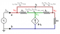
Hey guys well this seems to have become quite the discussion. I went back to my lecturer again. He taught me a new theory he made himself. He calls it "the golden rule." It can be used to calculate any thevinens.

He calculated this as 6ohms.

I think he left a lil mistake in it to test me. I calculated it at 5 ohm


WBahn

Joined Mar 31, 2012
32,873
6 Ω is correct.

Unless his name is "Mesh", he did not come up with this himself. ;)

Normally, before you start dealing with circuits having dependent sources, you should have gone through Mesh Current Analysis (MCA, which is nothing more than a systematic application of KVL), Node Voltage Analysis (NVA, which is nothing more than a systematic application of KCL), and superposition. Usually you are introduced to these early on in a Circuits I course using just independent voltage and current sources and resistors. As part of this you learn how to deal with current sources on interior branches when doing MCA using "super meshes" and you learn how to deal with voltage sources connected between two non-reference nodes when doing NVA using "super nodes".

Have you not done this yet?
 

Thread Starter

KevinEamon

Joined Apr 9, 2017
284
haha his name is not Mesh. I think he said he has not seen this type of analysis in any books. It's not just simple mesh. The current I in this case = Rth.
I = Rth.

hmmm. iI can't see my mistake. It's on that top loop there. But I am determined it should be 5 ohms. Even though I know I'm wrong.

hmmm can u please please please point out my mistake Wbahm. I have so much more to do.
 

WBahn

Joined Mar 31, 2012
32,873
Oh, did you every sit down and finish solving it using the four equations in four unknowns that you had (once we added the missing V1 = V3 equation)? You were extremely close at that point.

You had (ignoring the egregious sloppiness in units)

\(
2i_x \; = \; 3V_1 \; - \; 2V_2
i_x \; = \; -V_1 \; + \; 2V_2 \; - \; V_3
i_x \; = \; V_2 \; - \; V_3 \; + \; 1
\)

With V1 = V3 and knowing that we want V3, we can trivially eliminate V1 from these to get:

\(
2i_x \; = \; 3V_3 \; - \; 2V_2
i_x \; = \; -2V_3 \; + \; 2V_2
i_x \; = \; -V_3 \; + \; V_2 \; + \; 1
\)

If we add the first two together we get

\(
3i_x \; = \; V_3
\)

If we multiply the third equation by 2 and subtract the second one from it we get

\(
i_x \; = \; 2
\)

Substituting this into the prior one we get V = 6.

If your algebra skills are not up to this level of challenge, then you really need to put in the effort to deal with that. Weak math skills, particularly algebra, will make your life a nightmare in this field.
 

WBahn

Joined Mar 31, 2012
32,873
haha his name is not Mesh. I think he said he has not seen this type of analysis in any books. It's not just simple mesh. The current I in this case = Rth.
I = Rth.

hmmm. iI can't see my mistake. It's on that top loop there. But I am determined it should be 5 ohms. Even though I know I'm wrong.

hmmm can u please please please point out my mistake Wbahm. I have so much more to do.
I is NOT equal to Rth!

It is completely and totally nonsensical to claim that a current is equal to a resistance.

How much current is 3 ohms?

How much resistance is 2 amperes?

Nonsense!

What if I were to claim that the distance between New York and Los Angeles was 100 gallons or that my dog weighs thirty inches.

Nonsense!

You also need to learn how to look over your work and find your mistakes -- you do that by looking over your work and finding your mistakes. Having others always point them out to you does you a disservice in the long run.

It appears that you have at least two math errors and one conceptual mistake.

Where does the claim that

ix - i - (i - ix) = 0

come from?
 
Last edited:

Thread Starter

KevinEamon

Joined Apr 9, 2017
284
lol I know... but the dang thing works! I will show you another one he did for number 11 when I get home. That's why I said it was his own theory
 

WBahn

Joined Mar 31, 2012
32,873
It is NOT his own theory! He is applying very simple, very basic circuit analysis. If he is claiming that I = Rth he is also being inexcusably sloppy with his units and teaching you to be just as sloppy.
 

WBahn

Joined Mar 31, 2012
32,873
It's probably my fault. Not explaining it. This is the theory.

V= K1 I + K

where K1 = Rth
and K2 = Vth
The "theory" is better known as "Ohm's Law".

Take a circuit consisting of a voltage source, V, connected to a circuit having a resistance, Rth, in series with another voltage source Vth.

What is the current flowing out of the first source and into the resistor?

Ohm's Law: I = (V - Vth) / Rth

Solve for V

V = I·Rth + Vth
 

xxxyyyba

Joined Aug 7, 2012
289
KevinEamon, if you solve system of equations I derived for you, you will get It=Vt/6. Rth=Vt/It=6 Ohm.
I completely agree with WBahn, math is essential here. It's not possible to become electrical engineer without being VERY good at math.
 

Thread Starter

KevinEamon

Joined Apr 9, 2017
284
mmm my math is sufficient. Usually around 60 to 70%. If it's not good enough I will make it good enough. I am not afraid of hard work. Give me time I am only a lil n00b. :(
 

MrAl

Joined Jun 17, 2014
13,708
If the coefficient on the CCCS is infinite, then the only possible finite solution is for ix to be identically equal to zero, meaning that both the sense wire and the dependent source are open circuits. However, while at first glance this looks like the result is a 4 Ω equivalent resistor, that would put all of the current through the two 1 Ω resistors which would put a voltage across the sense wire, which is inconsistent with no current in it. To have no current in the sense wire, the input voltage must appear across the 2 Ω resistor. But the current in the 2 Ω resistor must come through the right hand 1 Ω resistor, which will raise it up above the input voltage, resulting in the same amount of current flowing to the left through the left hand 1 Ω resistor. Since this current has nowhere to go except into the input source, the actual equivalent resistance is -2 Ω. Notice that even though ix is zero, the output of the CCCS is twice the current in the 2 Ω resistor. This is merely a case of zero times infinity, which is mathematically indeterminate, working out to a finite value in the limit.

If the coefficient is zero, then ix can be anything and the CCCS will be an open. This makes the circuit equivalent to a +2 Ω resistor.

Presumably there is a value of the coefficient between 0 and infinity for which the equivalent resistance looks like an open circuit. This would require that the current in the 2 Ω resistor to be split evening between ix and the current in the right hand 1 Ω resistor so that these currents cancel at the input side, thus requiring the input voltage source to output nothing. This means that the CCCS is outputting twice whatever ix is, so at a coefficient of 2 the equivalent resistance is infinite.

Just as there is a value of the coefficient for which the equivalent resistance is infinite, there is probably one at which it is zero. This would require ix to be infinite, which will also result in an infinite voltage across the CCCS (so that it can produce an appropriate infinite current in the two 1 Ω resistors. Since it will have zero input resistance, the voltage across the input will be 0 V and there will be no current flowing in the 2 Ω resistor. That means that ix has to flow into the right hand 1 Ω resistor and, by symmetry, ix also flows into the center node from the left hand 1 Ω resistor. The result is that the current in the CCCS is twice the current in ix, but flowing in the opposite direction. Thus the coefficient is -2.

So the input resistance will be positive and finite between a coefficient of -2 to +2. It will be zero at -2 and infinite at +2. The input resistance will be negative outside of those limits.

Since the voltage across the top of the T formed by the CCCS and the two horizontal resistors is zero, all the matters is the ratio of those two resistors (the magnitude is masked by the current source that is effectively in series with them). Thus, the value of the input resistance depends only on the CCCS gain, the right-most resistor (the 2 Ω resistor), and the ratio of the two horizontal resistors.

Hi again,

I see you got interested in this circuit too :)
It is sometimes amazing how interesting these little circuits can be.

I was thinking of redrawing this one as a current mode op amp circuit. Like maybe with the old and gone LM3900 (i think that was it) op amp. I liked that op amp and was sad to see it disappear.
The internal gain of the op amp would be the current source gain (and possibly a voltage controlled current source output stage added to make up for the output of the op amp being more like a voltage source).

We've gone way beyond the original question, but it did become more interesting that way :)
Also reminds me of a zero voltage current shunt i had designed years ago to get rid of that pesky always-present voltage drop of all current shunts.
 

Thread Starter

KevinEamon

Joined Apr 9, 2017
284
Oh yeh sorry forgot about that.

Hopefully it should be good. Corresponds with the answer the lecturer got, which is always a good sign.

 
Top