Facebook
 Google
 GitHub
 Linkedin
What about something like this?Hi again,
Well if we define the 'inrush' current as a current that increases very fast but then after a somewhat sort time it decreases to some normal level, then we want to detect the higher current and then after a delay (where we assume the current has then decreased) turn the relay on to short out the limiter component (resistor or thermistor). That might help to think about this clearly.
What this means is that the comparator will be set at some level with a voltage reference (like a zener) and when the voltage gets over that value it starts the delay countdown. The voltage is of course developed from across the limiting resistor or thermistor, or perhaps a second resistor just to sense current.
If the output of the comparator is normally 0 volts, then when the current shoots up the voltage across it shoots up, and the comparator output goes from 0 volts to say 5 volts and that starts the delay. After the delay period, the relay coil turns on and a second set of contacts bypasses the delay and comparator and keeps the relay turned on.
This means the comparator needs to have enough built in hysteresis to keep the relay energized for enough time so the relay contacts actually close, or that alone keeps the relay turned on.
Just for example, let's say we are using a 1 Ohm sense resistor which also limits the current, and say the normal current is 1 amp and the surge is 2 amps. That develops 1 volt and 2 volts respectively.
If the comparator is set for 1.6 volts (detecting 1.6 amps) then when the current goes to 2 amps that trips the comparator and the output goes to +5v thus initiating the turn on of the relay. Now say the current drops to 1 amp, then the relay contacts actually close. The comparator lower limit would be set to say 0.5 amps, and so it will remain with the output at +5 volts. Only when the system is shut off will the comparator and thus the relay be reset to the starting state.
So in this example we set the upper limit of the comparator to 1.6 volts and lower limit to 0.5 volts. We can look at the formulas for those settings. It involves the usual comparator connections plus an extra resistor from the output of the comparator to the non-inverting input of the comparator, which will also have other resistors connected to it.
The calculation for the hysteresis resistor value is not that difficult. When you come up with the basic circuit you can post that and then we'll look at calculating that resistor value.
Is this the correct path to follow?

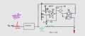
1. 60A spike arrives in red
2. 10 ohm NTC limit it to 6A on horizontal line because relay is still open
3. Relay closes and input signal will follow purple path, bypassing NTC
I don't know if I have made myself clear, but the relay must remain closed forever after NTC has done its work. It seems to me that in this circuit the closure of the relay given by the comparator lasts a "limited" period of time before the comparator reopens (?)