 Facebook
 Google
 GitHub
 Linkedin
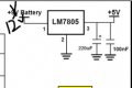
All output pins should be close to zero volts when not High.
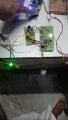
Not sure why those voltages are erratic like that but not surprised with all that wiring between boards.
Do you have capacitors on the input and output pins of the 7805 regulator ICs?
Decoder Encoder With 4017 Circuit Without Microcontroller.
- Thread starter KRAB
- Start date


| Thread starter | Similar threads | Forum | Replies | Date |
|---|---|---|---|---|
| K | Decoder encoder using 4017 with IR LED For transmitter | General Electronics Chat | 14 | |
| D | HOLTEK encoder and decoder | Wireless & RF Design | 9 | |
|
|
Encoder and decoder for remote control (RC car) | Digital Design | 17 | |
| I | Encoder/Decoder (Logisim) | Homework Help | 1 | |
| A | encoder/decoder Ir/Rf remote control | General Electronics Chat | 1 |


