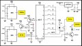
Decoder Encoder With 4017 Circuit Without Microcontroller.

sghioto

Joined Dec 31, 2017
8,634
The oscilloscope is your best tool to troubleshoot this project.
Use the scope to the see what waveforms are present at those same locations.
I still suspect a noise issue possibly from the IR receiver .
 

Thread Starter

KRAB

Joined Aug 12, 2025
47
The oscilloscope is your best tool to troubleshoot this project.
Use the scope to the see what waveforms are present at those same locations.
I still suspect a noise issue possibly from the IR receiver .
i am not that much expert in handling scopes sir. Meanwhile, i want to meticulously check the 2N2222 and S850 on the pin level voltages and replace ic4093 with new one, ( may be some issue??) and then ... see if i progress.
 

sghioto

Joined Dec 31, 2017
8,634
Before replacing the 4093 I see an issue with the pcb.
All unused input pins on the 4093 should be grounded.
Connect pins 5,6,8,9,12 and 13 to Ground, it's important.
 

Thread Starter

KRAB

Joined Aug 12, 2025
47
Before replacing the 4093 I see an issue with the pcb.
All unused input pins on the 4093 should be grounded.
Connect pins 5,6,8,9,12 and 13 to Ground, it's important.
sure sir, i , it is actually 9 pins ( 3 trios )to be grounded as per advice,4,5,6 & 8,9,10 then,11,12,13

Note: it is crazy for me, the You tube who made this design not using pin 2 of IC4017, USED 4,7, 10 FOR SWITCHES IN Transmitter, where as i see the same connected to pin 2 in receiver. so, confusing for my understanding. hope you have some answer. Surprisingly, my head is still not able to figure out the theory and concept behind this one. But, i am happy, i saw it, getting a good nurturing from you, despite me a novice. i hope i will win sure. i love to complete successfully.
 

drjohsmith

Joined Dec 13, 2021
1,601
sure sir, i , it is actually 9 pins ( 3 trios )to be grounded as per advice,4,5,6 & 8,9,10 then,11,12,13

Note: it is crazy for me, the You tube who made this design not using pin 2 of IC4017, USED 4,7, 10 FOR SWITCHES IN Transmitter, where as i see the same connected to pin 2 in receiver. so, confusing for my understanding. hope you have some answer. Surprisingly, my head is still not able to figure out the theory and concept behind this one. But, i am happy, i saw it, getting a good nurturing from you, despite me a novice. i hope i will win sure. i love to complete successfully.
I think that says more about the level of the designer on u tube your following .
This circuit is as others have discussed very marginal , and a terrible circuit .
It's a credit to @sghioto etc all that you are this far.
 

sghioto

Joined Dec 31, 2017
8,634
Note: it is crazy for me, the You tube who made this design not using pin 2 of IC4017, USED 4,7, 10 FOR SWITCHES IN Transmitter, where as i see the same connected to pin 2 in receiver. so, confusing for my understanding. hope you have some answer
Here's why that is.
When button #1 (pin4) is pressed on the transmitter the PC817 is turned ON and the first pulse from the 24 Hz oscillator is counted.
This same pulse simultaneously activates the IR LED driver sending a burst of 38KHz to the receiver.
The second pulse when counted immediately makes pin4 go High which turns OFF the PC817 and the IR LED driver so only one burst of 38KHz is sent.
IR receiver sees only 1 pulse, which makes pin2 on the receiver 4017 go High.
Same for the other two buttons. To send 2 pulses requires output on pin7 and 3 pulses output on pin10.
 

Thread Starter

KRAB

Joined Aug 12, 2025
47
I think that says more about the level of the designer on u tube your following .
This circuit is as others have discussed very marginal , and a terrible circuit .
It's a credit to @sghioto etc all that you are this far.
sorry for my delayed response. You are right on the dot. The inputs and obssessed interest to support and nurture by sghioto had been stupendous( my english not great though) and tonnes of thanks to the entire supporting hearts and to sghioto in particular. Relentlessly the replies are meticulously fast and a great hand walk. The fear in me that i am alone is fading out in this specific project. Thanks to the SMEs conducting and supporting people like me.
 

MrChips

Joined Oct 2, 2009
34,816
ok, sir, sure i will not, thanks for that input. sometime i remember on an another blog, they advicing to short all unused pins. so, sorry for that.
Don't blindly believe everything you read on the internet. Having an in-depth understanding of each situation will allow you to make decisions for yourself and avoid making mistakes.

"short all unused pins" - this is incorrect.

Here is the correct answer.
Do not connect unused output pins. Doing so can cause excessive current to flow through the output driver device.

Connect unused input pins to a valid logic level voltage. Read the device datasheet to determine what logic level voltage is appropriate for that specific input pin, in other words, a logic LOW or logic HIGH voltage source. In some circumstances, a series resistor is recommended in order to limit the input current.
 

Thread Starter

KRAB

Joined Aug 12, 2025
47
i am back after working on the inputs given by you all. I get the LED Glowing and stopping now. In addition, i measured with multimeter the outputs from IC4093 PIN 3. The multimeter readings go from 0 to a max. 2.50 to 2.58. While, i am happy that a button press, on IR Transmitter is captured by the IR Receiver and the IC4093 Pin giving an output. Up to this stage, it goes well. This signal is a trigger to IC4017, but i do not see output from pin 4 . not sure why. there is a small output voltage fluctuation that indicates something happening. but... could you help me where i get struck pl. thank you.
 

Attachments

sghioto

Joined Dec 31, 2017
8,634
First question, why are there 4 circuit boards?
When button 1 on the transmitter is pressed the output should be seen on pin2 of the 4017 in the receiver.
 

Thread Starter

KRAB

Joined Aug 12, 2025
47
First question, why are there 4 circuit boards?
When button 1 on the transmitter is pressed the output should be seen on pin2 of the 4017 in the receiver.
sir, you right. to avoid buidling new PCBs or tinker out the design that we review, and time, i use the already built boards to ensure i am able to demonstrate it. yes it is sometimes frustratig. But it saves time and multiple reworks for me. As i said earlier, i am not a good breadboard assembler. so, make some PCBs to get the right cirucit proved. having said, that i had used pin 4, 7, 10 as output points sir. not considered pin 2 at all.
 

Thread Starter

KRAB

Joined Aug 12, 2025
47
The outputs are:
pin2 for button 1
pin4 for button 2
pin7 for button 3
sir, thanks. May i share what is my understood mindset with you on this aspect please.
Here where there is a misnomer for me or my understanding. The U Tube design for transmitter has its switches on pin no 4, 7, 10, 1, 5, 6, and finally 9. ( Yes the pattern is as per the IC 4017 Prescription). He used output pin 3 for autoreset ( not sure i understood the underlying logic but ok). He never used pin 2 anywhere sir. But, for choice of user, he starts from 4 onwards. Hence, in my view, i avoided using pin 2 in Transmitter since it is not there in circuit or in the tracks ( U- Tube picture).
My assumption , if i press pin 4 in transmitter, the output pin 4 will be selected in receiver and thus the expected output. Same assumption holds good for succeeding pins per the circuit.

To my surprise,the receiver side he had used pin 2 as the first selection and that bowls me out and my CATCH22 Situation sir.
Thanks.
 

Attachments

Thread Starter

KRAB

Joined Aug 12, 2025
47
Does this mean you understand the circuit design better?
Is the circuit working correctly now?
No sir, i wish to correct myself and assumed things, my understanding could be wrong as well. pl. excuse.

Is the circuit working correctly now?
I am working on it sir. would be useful, if i can be clarified on those anomalies.
 

sghioto

Joined Dec 31, 2017
8,634
What exactly do you need to know at this juncture?
Do you have LEDs connected to output pins 2,4 and 7 on the 4017 receiver for circuit verification?
 
Last edited:

Thread Starter

KRAB

Joined Aug 12, 2025
47
What exactly do you need to know at this juncture?
Do you have LEDs connected to output pins 2,4 and 7 on the 4017 receiver for circuit verification?
Sir, i tested and reconnected the mistakenly used pin 10 for pin 2 and checked. seems now I see a light at the end of tunnel. I am yet to connect LEDs separately, but measured the wires that i will connect to LEDs later. for HIGH Voltages. yes they work. But when i press one switch, and measured voltages on all the pins separately and put in the matrix. nothing is 0.0 volts but goes up to 1.1volts also. thank you. i will connect ith the LED and do it as well. Thank you very much.
 

Attachments

sghioto

Joined Dec 31, 2017
8,634
nothing is 0.0 volts but goes up to 1.1volts also.
All output pins should be close to zero volts when not High.
Not sure why those voltages are erratic like that but not surprised with all that wiring between boards.
Do you have capacitors on the input and output pins of the 7805 regulator ICs?
 
Top