Debounce... To ReSchmitt or not to ReSchmitt....

shortbus

Joined Sep 30, 2009
10,049
Probably one of my many dumb statements, but isn't what is shown in the first post known as a "half monostable", "one shot" or "edge detector"? Didn't realize they also functioned as a debounce circuit. Thought they were only used to give a pulse then go back to the original state.
 

Thread Starter

2DrTahoe

Joined Dec 14, 2016
40
Not sure. If you Google the subject of debouncing a switch, this circuit is the one that is used and is well documented with before and after scope results.
 

eetech00

Joined Jun 8, 2013
4,723
Negative. The ssr is LCC110. It is a Form C relay the will control the "on" function of the pwm's. This is a manual switch.
I know others suggested no debounce is needed but after reviewing the data sheet that is a fast device. The input can switch in less that 1ms. Most good mechanical switches won’t bounce after 20ms. I recommend to debounce if driven by mechanical switch. A 100 ms debounce delay would cover just about any decent mechanical switch.

eT
 

AnalogKid

Joined Aug 1, 2013
12,232
isn't what is shown in the first post known as a "half monostable", "one shot" or "edge detector"?
Close. It's actually a pulse stretcher that has the effect of being a lowpass filter. The output of the input circuit (the signal going into the logic gate input) is the same logic polarity as the switch; it goes low almost immediately when the switch is closed, but it returns to the rest state a time interval after the switch opens. So if the circuit time constant is 50 ms and you hold the switch closed for one s, the gate input sees a low of 1.050 s.

A fallout of this, and the reason it works as a switch debouncer, is that if, after the initial switch contact closure, the switch contacts open and close very rapidly (bounce) with each open and close cycle less than 50 ms, the R-C network filters these and the logic gate does not see them, because the switch has to remain open for a minimum of 50 ms, the circuit time constant.

ak
 

eetech00

Joined Jun 8, 2013
4,723
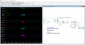
Here is an example. This shows the switch bouncing about 20ms (a good switch).

Debounce_Test_74HC14.png

If you do decide to debounce, its better to use a 74HC14 because I can provide more current to drive the LCC110. The LCC110 needs at least 8ma to turn on. The CD40106B can only output 6.8ma and would require a external drive transistor.

eT
 

AnalogKid

Joined Aug 1, 2013
12,232
If the circuit is running on 5 V, I recommend changing to AC series logic. The 74AC14 (or ACT14) can source and sink 20 mA per output. It is a great LED driver in circuits such as this.

ak
 

AnalogKid

Joined Aug 1, 2013
12,232
I need to knock down the 5v to approximately 1.2v for the control side of the relay via a voltage divider circuit.
Not a voltage divider, just a current limiter. 1.2 V is the forward voltage of the internal LED when on. To drive it with a 5 V source, a 330 ohm resistor will cause a current of 11.5 mA. Check the relay datasheet to see if this is within the recommended operating range, and adjust as needed.

ak
 

eetech00

Joined Jun 8, 2013
4,723
The thing I don't like about this type of debounce circuit is that there is a momentary spike on power up as the circuit initializes and the output will momentarily go high. Not a problem if using a POR circuit.

eT
 

AnalogKid

Joined Aug 1, 2013
12,232
The thing I don't like about this type of debounce circuit is that there is a momentary spike on power up as the circuit initializes and the output will momentarily go high.
There is a simple way around that. The problem with the circuit is that the switch and the cap are both tied to the same rail (GND in this case). That means that the power-up condition for the cap is the same as when the switch is *pressed*, not released. The solution was mentioned by Wally - move the switch such that it pulls the cap up to Vcc. In this way, the initial state of the cap is the same as the resting state of the cap so there is no turn-on glitch.

ak
 

Thread Starter

2DrTahoe

Joined Dec 14, 2016
40
Ah, ok on the current limiter.

But then, back to my original post...if the debounce circuit requires a low switch and I only can switch a high signal, then i would have to put it through a Schmitt after the switch to give the debounce what it needs to see. Yes?
 

eetech00

Joined Jun 8, 2013
4,723
Ah, ok on the current limiter.

But then, back to my original post...if the debounce circuit requires a low switch and I only can switch a high signal, then i would have to put it through a Schmitt after the switch to give the debounce what it needs to see. Yes?
No...you can easily change the circuit to produce a low output when the switch is closed (as mentioned in post #2)
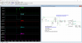
Like this:

Debounce_Test_74HC14_Pos_Input.png


You can also reverse the connections to the LCC110 diode to invert the input to the LCC110.

Also, the 74HC14 will work but a 74AC14 would be a better choice as mentioned in post #26.

eT
 
Last edited:
Top