Facebook
 Google
 GitHub
 Linkedin
That is the question! Actually that is not the question but it is related.
OK, so here goes. I'm a novice and am trying to get this through my thick skull. Below is the Debounce circuit I want to use. I understand the need of the components and the outcome. In short, the Schmitt trigger (a CD40106 hex inverting Schmitt trigger IC) smooths out the signal and inverts the input. So with the switch open, the output is Negative (low) , when closed the output is Positive (high).
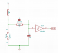
In my case, I do not need the output pin to be held neither high or low. Off is just fine.. But, according to the schematic it requires a 5v+ feed and if its not there, there will be a LOW signal going to the Schmitt via the Capacitor causing a HIGH output from the Schmitt.... I think. I think this because the IC has its own supply of power to perform the logic function.
Here is my problem. I will be switching a HIGH signal, 5v+ via a SPST switch. Since the "trigger", "switch", "connection" has to be a negative input to close the Debounce circuit, then I would need to invert the signal through another Schmitt to make it LOW going into the Debounce circuit. This would provide what the Schmitt in the Debounce circuit needs thus resulting in the circuit being closed LOW, the Schmitt inverting the signal AND providing a HIGH output which is the result I need.
I thought that maybe I could just switch "on" the original 5v+ feeding the Debounce circuit and make the LOW "switch" in the circuit permanent and all would work. However, I go back to that LOW connection through the Capacitor that the Schmitt see's.
So my question is, can I just use the switch to provide the 5v+ to the Debounce circuit with the LOW side of the circuit permanently closed to ground and get the desired HIGH output from the Schmitt OR do I really need to blindly provide an inverted signal to the Debounce circuit and keep things to the original schematic?
I hope I was clear on this.
Thanks.
OK, so here goes. I'm a novice and am trying to get this through my thick skull. Below is the Debounce circuit I want to use. I understand the need of the components and the outcome. In short, the Schmitt trigger (a CD40106 hex inverting Schmitt trigger IC) smooths out the signal and inverts the input. So with the switch open, the output is Negative (low) , when closed the output is Positive (high).
In my case, I do not need the output pin to be held neither high or low. Off is just fine.. But, according to the schematic it requires a 5v+ feed and if its not there, there will be a LOW signal going to the Schmitt via the Capacitor causing a HIGH output from the Schmitt.... I think. I think this because the IC has its own supply of power to perform the logic function.
Here is my problem. I will be switching a HIGH signal, 5v+ via a SPST switch. Since the "trigger", "switch", "connection" has to be a negative input to close the Debounce circuit, then I would need to invert the signal through another Schmitt to make it LOW going into the Debounce circuit. This would provide what the Schmitt in the Debounce circuit needs thus resulting in the circuit being closed LOW, the Schmitt inverting the signal AND providing a HIGH output which is the result I need.
I thought that maybe I could just switch "on" the original 5v+ feeding the Debounce circuit and make the LOW "switch" in the circuit permanent and all would work. However, I go back to that LOW connection through the Capacitor that the Schmitt see's.
So my question is, can I just use the switch to provide the 5v+ to the Debounce circuit with the LOW side of the circuit permanently closed to ground and get the desired HIGH output from the Schmitt OR do I really need to blindly provide an inverted signal to the Debounce circuit and keep things to the original schematic?
I hope I was clear on this.
Thanks.