DC motor help

Thread Starter

garjess

Joined Jan 23, 2026
9
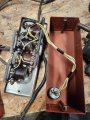
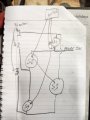
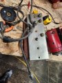
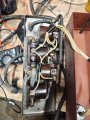
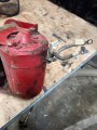
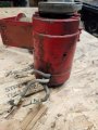
I just acquired this motor/winch. Im assuming its DC, just from the size of the wires. The winch doesn't have any controls so the motor must be able to turn in forward and reverse. The only labels are the wires are labeled 1,2,and 3 with some masking tape.
How do I figure out which wire is ground and I'm assuming which two are positive?
 

Attachments

schmitt trigger

Joined Jul 12, 2010
2,083
You are absolutely doing the right thing; asking before connecting it to a battery.
Get yourself a 12v incandescent bulb, 50 or so watts like the headlights, and put it in series with the battery’s positive output.

Now you can connect the motor in all possible wiring combinations without fear of causing a short. The lamp will glow dimly and the motor will turn slowly one direction or the other with correct connections. If a wiring combination is invalid, the lamp will glow bright and the motor may buzz, but no harm will occur.
 

Thread Starter

garjess

Joined Jan 23, 2026
9
You are absolutely doing the right thing; asking before connecting it to a battery.
Get yourself a 12v incandescent bulb, 50 or so watts like the headlights, and put it in series with the battery’s positive output.

Now you can connect the motor in all possible wiring combinations without fear of causing a short. The lamp will glow dimly and the motor will turn slowly one direction or the other with correct connections. If a wiring combination is invalid, the lamp will glow bright and the motor may buzz, but no harm will occur.
Thanks, I'll try the light bulb. Am I correct in thinking it should be one ground and the other two wire are positive, one for forward and one for reverse?
 

MaxHeadRoom

Joined Jul 18, 2013
30,643
If one is ground, there will be continuity to the frame.
Spin it by hand and see if it generates a DC voltage, IOW is it DC or AC (ie no voltage generated !)
Wouldn't be three phase By any chance?
 
Last edited:

B-JoJo-S

Joined Jan 3, 2026
290
DC motors from treadmills have permanent magnets in them and two wires. Power one way (Pos to one wire, Neg to the other) and the motor will spin. Three wires confuses me. Like MaxHeadRoom suggested, spin the motor by hand if you can while watching for a voltage on the wires. IF it is a permanent magnet motor you will see a voltage.

Someone said there might be a brake circuit. Possible. But I'm thinking it's probably an AC motor, 3-phase. BUT you said it's a wench motor. But nothing on how it's powered. With a 3-Phase AC motor you can change the direction by changing just two of the wires. A-B-C may drive the motor one way while A-C-B will drive it the other way. Any two of the wires change the direction of a 3-Phase motor.

You asked how to determine which wire is ground. In a 3-Phase motor with three wires there is no ground, not that I'm aware of. A fourth wire that is grounded to the frame would be required in order for it to be safe.

Do we know it's 12 volts?
 

Thread Starter

garjess

Joined Jan 23, 2026
9
I went back to the estate sale where I bought the winch and found the controller for it. It's definitely DC, the controller has car battery leads. Thankfully the controller wires are still labeled and match the motor.
 

MisterBill2

Joined Jan 23, 2018
27,491
IAnd now that the TS has the controller it would be interesting to see a report on how it works. t had to be a lower voltage DC motor, based on the size of the leads and the size of the motor. In the one photo we see a drum at right angles to the motor axis, implying that there may be one worm gear reduction stage, That implies that it does not require a brake.
I suggest a carefu examination of the insulation on those wires in the area that they enter the motor.
AND let us see the control box, which was a very good choice to go back and get it.
 

Thread Starter

garjess

Joined Jan 23, 2026
9
It looks like a 12v starter motor to me. I'm going to open up the control box next and see what's inside. I can't believe I found the control box in this basement that is completely packed with stuff. I'm guessing there is two starter solenoids providing forward and reverse. It will be tomorrow before I get to that. I'll post some pics of what I find.
 

MisterBill2

Joined Jan 23, 2018
27,491
It looks too old to be a PM field motor, but it does look like a brush and commutator type. My guess is onlead is for the field and the other two are for the brushes, to be reverse able. BUT it might also have two sets of field coils.
 

MisterBill2

Joined Jan 23, 2018
27,491
normally with a wound field shunt motor, there are four leads, the field being fairly high resistance compared to the com.
In a variable high load application it will probably be a series-field motor, with one end of the field grounded to the case, and both brushes connected externally. Hence the three heavy wires. definitely NOT CNC style!!
 

Thread Starter

garjess

Joined Jan 23, 2026
9
Any chance you can reverse-engineer to a legible schematic?
Do you know what fed the control box previously?
The power in was from a car battery. There is a battery cable for the positive. There are two wires hooked to the ground post. I assume one goes to the battery and the other to the motor but I sure dont see any where missing paint where a cable was hooked up
 

Attachments

Thread Starter

garjess

Joined Jan 23, 2026
9
The power in was from a car battery. There is a battery cable for the positive. There are two wires hooked to the ground post. I assume one goes to the battery and the other to the motor but I sure dont see any where missing paint where a cable was hooked up
The base of all solenoids are grounded to the box
 
Top