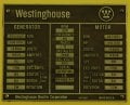
The generator output is line to line and that is the voltage applied to the bridge. My scheme avoids the the un-usable and not needed neutral and extra computation of the L-N voltage. As I said, any rotating machine nameplate gives the rating in L-L volts and line amps. A 3 ph transformer will be rated the same way. Some 'smaller' transformers that are loaded L-N will have a dual voltage rating like 208/120 or 480/277.
Only 2 L-L voltages (generators) are needed because Kirchoff guarantees that the 3rd phase is the sum of the other 2. Since we're only interested in the output there is no need to model the generator in any detail, only the function is modeled. Impedance could be added in the lines T1 thru T3 to model line drop if desired. The only thing special was using peak voltage rather than the usual RMS that would be on the nameplate. This is because the Spice SINE function requires the peak value.
A fixed load resistor should be okay for your simulation purposes.
You reduce ripple (if needed) by increasing the filter capacitance and/or adding a larger inductor (but with the inductor at the input to the capacitors).
There's no other magic to reduce ripple.
For some reason you grounded the three voltage sources. D2/D4/D6 will die instantly and, assuming the diodes fail open circuit in real life, you are left with a half-wave rectifier. Look at the frequency of the output voltage ripple .
Hello, and apologies for pressing the point, but in my example simulation, the three input generators represent the motor phases, so in reality they are connected to a neutral, not to gnd.
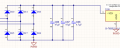
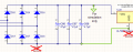
Could you confirm that the three lower diodes of the rectifier should instead be connected to earth, as shown in the photo?
Hello, and apologies for pressing the point, but in my example simulation, the three input generators represent the motor phases, so in reality they are connected to a neutral, not to gnd.
Could you confirm that the three lower diodes of the rectifier should instead be connected to earth, as shown in the photo?
Symbol GND used by LTspice as reference point with potential 0V.
You can, for example, put it to + of power supply, LTspice will still working just fine.
In real life - it is your choice to ground or not to ground your circuit.
Yes.
GND is simply the 0V reference point for Spice, nothing else.
It is not referencing an "earth" ground which is a physical connection that the real circuit may or may not have.
Since all voltages are between two points, without at least one GND point in the circuit Spice cannot calculate the node voltages, which are always referenced to GND, and will usually give an error notice of that.

 Facebook
 Google
 GitHub
 Linkedin