 Facebook
 Google
 GitHub
 Linkedin
hi EZ,
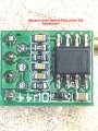
Look at this image, do the resistance check. [ module NOT powered]
Also when powered ON, [ with no external connection to the Vi/Trig pin] what voltage do you measure on Pin 2 of the 555.
E
Look at this image, do the resistance check. [ module NOT powered]
Also when powered ON, [ with no external connection to the Vi/Trig pin] what voltage do you measure on Pin 2 of the 555.
E
Attachments
-
 1.4 MB Views: 15


