Dc circuit help

Thread Starter

ElctronicZombie

Joined Jan 19, 2020
47
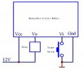
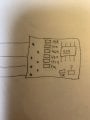
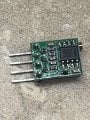
OK, this is a totally undocumented device from China. It may or not use a 555 timer IC, and there is no way to modify it. And my guess is that the TS is not in a position to make changes. Probably the sensor also is undocumented and so there is a case of really not knowing what we are working with,
 

Attachments

MisterBill2

Joined Jan 23, 2018
18,167
OK, now we can see that the IC is labeled as a 555, but is there any information at all on how to use or connect that board? I did not think that there was. So how can anyone know what the actual circuit is, or how it is supposed to function. And that one chip resistor at such an angle may not be connected correctly.
 

ericgibbs

Joined Jan 29, 2010
18,766
hi EZ,
The edited circuit I posted should work, it is a very common method of triggering a 555.
You must have a problem elsewhere.?

Does the circuit PCB work when using a push button.?
E
 

Thread Starter

ElctronicZombie

Joined Jan 19, 2020
47
hi EZ,
The edited circuit I posted should work, it is a very common method of triggering a 555.
You must have a problem elsewhere.?

Does the circuit PCB work when using a push button.?
E
push button does not work either, must be something in the way that the dw44 is designed, as I have 2 different dw44 and both don’t work with push button (with the schematic you sent with push button where the optical sensor is)they only work if I ground out Vi and then they both work as they should. So either I find a way to convert my optical output to a ground (ie relay or something) or look for another timer that has adjustable time on it that will trigger on a low voltage from my optical output.
 

MisterBill2

Joined Jan 23, 2018
18,167
Did the module ever work with a push button connected that way? Do you have a meter to read the voltage across the buttonn terminals with the button NOT pushed?
I think at one point it was stated that the timer worked with the button but not the sensor. Have things changed?
 

Thread Starter

ElctronicZombie

Joined Jan 19, 2020
47
Did the module ever work with a push button connected that way? Do you have a meter to read the voltage across the buttonn terminals with the button NOT pushed?
I think at one point it was stated that the timer worked with the button but not the sensor. Have things changed?
No the modular has never worked with the button. With button not pushed I have 0v on one side 5v on other side of the button. But the dw44 timer with just power hooked to it not other modular and in its normal state it has 5v to ground on Vi
 

Attachments

Thread Starter

ElctronicZombie

Joined Jan 19, 2020
47
hi EZ,
How did you determine the pin out of the DW44 module, I looked online and could not find a wiring diagram.?
E
I found this
https://www.evselectro.com/ne555-dw44-monostale-delay-circuit-module-dc-5-15v-10ms-20s-7906
And
http://www.ohmslawcalculator.com/555-monostable-calculator
And the picture
With those combined pitches and drawing Which I cannot say there right or not but again the only way that I get it to function properly is to ground out Vi as per those pictures.
 

Attachments

ericgibbs

Joined Jan 29, 2010
18,766
hi,
Checked your image, also I found a very poor quality image, which showed the same pin out.

I have modified that circuit in the image, build this, using a switch, exactly as shown, does it now work .?
E
AAA 135 10.20.gif
 

MisterBill2

Joined Jan 23, 2018
18,167
I suggest connecting the relay between the Vo terminal and the -12 volts terminal, marked as "GND". That does make more sense. And if the timer has not worked previously, the fault may be with the timer board. Also, in the one image that shows the input and output waveforms, Vo is shown as going positive, and that DEFINITELY means that the relay coil connects between Vo and Gnd. The circuit in that picture does not even show an output terminal, only an LED, so it is not an accurate representation of the module at all.
 
Last edited:

MisterBill2

Joined Jan 23, 2018
18,167
I found this
https://www.evselectro.com/ne555-dw44-monostale-delay-circuit-module-dc-5-15v-10ms-20s-7906
And
http://www.ohmslawcalculator.com/555-monostable-calculator
And the picture
With those combined pitches and drawing Which I cannot say there right or not but again the only way that I get it to function properly is to ground out Vi as per those pictures.
Please explain exactly what you mean by "ground out", because really that is a bit unclear. Where does the Vi terminal connect when you do that? I made a guess, but it may not be correct. And as I look at the circuit some more it does not seem reasonable that the timed output would be a voltage between the supply terminal and the Vo terminal.
 

Thread Starter

ElctronicZombie

Joined Jan 19, 2020
47
Please explain exactly what you mean by "ground out", because really that is a bit unclear. Where does the Vi terminal connect when you do that? I made a guess, but it may not be correct. And as I look at the circuit some more it does not seem reasonable that the timed output would be a voltage between the supply terminal and the Vo terminal.
Ok to clear up ground out means I touch Vi to - side of power supply or the terminal marked GND, also when the timer is active/running I have 5v on Vo of timer/dw44 which sends signal to the l298n board which runs motor. And this is the only way I can get the timer/dw44 to operate.
 

ericgibbs

Joined Jan 29, 2010
18,766
Is there a possibility that the dw44 already has the resistors and capacitors to make the 555 timer operate as a monostable circuit?
Hi,
Can you draw a simple sketch of the DW44 module that shows the components value.
E
 

MisterBill2

Joined Jan 23, 2018
18,167
Ok to clear up ground out means I touch Vi to - side of power supply or the terminal marked GND, also when the timer is active/running I have 5v on Vo of timer/dw44 which sends signal to the l298n board which runs motor. And this is the only way I can get the timer/dw44 to operate.
Now I am wondering if possibly the time is set to zero. Have you adjusted the time setting to midpoint yet? That could be the problem, aside from the output possibly being a pull-up instead of a pull down. The description in the link on post #52 states that after triggering the output will go high. The way that the relay coil is connected between the V+ line and the Vo terminal, the relay will not ever operate. So that is one problem. If pushing that button does not trigger the timer then it may be that the button is not connected or it is a normally closed type. So there are two things to do, the first is to correct the relay coil connection and the second is to increase the time setting.
 
Last edited:

Thread Starter

ElctronicZombie

Joined Jan 19, 2020
47
Now I am wondering if possibly the time is set to zero. Have you adjusted the time setting to midpoint yet? That could be the problem, aside from the output possibly being a pull-up instead of a pull down. The description in the link on post #52 states that after triggering the output will go high. The way that the relay coil is connected between the V+ line and the Vo terminal, the relay will not ever operate. So that is one problem. If pushing that button does not trigger the timer then it may be that the button is not connected or it is a normally closed type. So there are two things to do, the first is to correct the relay coil connection and the second is to increase the time setting.
I have increased and decreased the time and it does work as it should but only when I touch Vi to -12/GND the motor will operate for different amount of time depending on how many turns on the adjustment screw. The push button I am using is a NO when not pushed and closed when I push verified by multi meter
 
Top