Facebook
 Google
 GitHub
 Linkedin
hi,
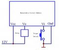
Measure and post the voltages at V1 and V2
For both sensor output conditions ie: when the sensor is outputting +5v and 0v
Also confirm the 555 Vsupply voltage.
E
Are both resistors 10k???? make sure.
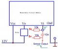
Measure and post the voltages at V1 and V2
For both sensor output conditions ie: when the sensor is outputting +5v and 0v
Also confirm the 555 Vsupply voltage.
E
Are both resistors 10k???? make sure.
Attachments
-
 2.4 MB Views: 8