 Facebook
 Google
 GitHub
 Linkedin
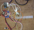
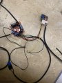
I have a signal output on a sensor that is 5vdc when open and 0v dc when closed, I need to send a ground signal to my timer board when sensor is closed because the input on my timer board trigger needs to see a ground to be triggered, any help would be great thanks.
Dc circuit help
- Thread starter ElctronicZombie
- Start date


| Thread starter | Similar threads | Forum | Replies | Date |
|---|---|---|---|---|
|
|
Piezoelectric sensor based BCG measurement | Sensor Design & Implementation | 5 | |
|
|
Logic D | Homework Help | 53 | |
|
|
Help to make a circuit for as battery disconnect from charger LED glow | General Electronics Chat | 5 | |
| J | Help with Arduino Circuit Programming | Programming & Languages | 13 | |
| S | Circuit Building Homework help | Homework Help | 23 |


